2023-11-10 04:11:46 Author: www.thezdi.com(查看原文) 阅读量:11 收藏
Previously, we looked at the ChargePoint Home Flex EV charger – one of the targets in the upcoming Pwn2Own Automotive contest. In this post, we look at how to safely modify an EV charger to perform research through benchtop experiments. This isn’t meant to be a comprehensive guide, but it should provide you with a solid base to start your own research into these devices.
In some of our previous blogs, we’ve looked at the attack surface of devices included in the Pwn2Own Automotive competition. In this post, we provide some information on hardware modifications that can be made to most electric vehicle (EV) chargers to assist in benchtop experimentation. But first, a safety reminder:
EV Chargers contain high voltages, use extreme caution when working with them. Never touch interior components when powered on. If you are unable to determine the safe vs unsafe regions within the device, seek qualified assistance before proceeding. An open enclosure can be a deadly enclosure. These modifications should not be made if there is an intent to ever plug into a vehicle or use the charging cable power or signal conductors as part of the experimentation. If there is such an intent, the EV charger should not be modified, and the appropriate connections should be made per the manufacturer's instructions. Additionally, these suggested modifications do not reduce the danger or the need to exercise caution and appropriate high-voltage safety precautions.
Most residential EV chargers arrive out of the box with both the input and output power cables attached to the unit. The power input will generally be a household appliance-type plug, and the charger output will likely be a cable with an SAE J1772 connector that plugs into the vehicle. The input power is typically high current and high voltage (230VAC). However, most researchers do not need a high current connection to power up the device when looking for bugs. You can use a cheap, pre-built power cable that can be sacrificed to avoid the cost of setting up a high current and voltage infrastructure by a licensed electrician just to power up the device under test.
Here’s a look at a typical input cable plug:
Figure 1 - Typical EV charger residential input cable plug
And here’s a typical output cable plug (SAE J1772)

Figure 2 - Typical EV charger output cable plug
These connectors and voltages cannot be easily or safely handled at an electronics bench, so the following modification steps aim to simplify some of this infrastructure for experimentation. As a reminder, these modifications should only be done on EV chargers meant for research. If you intend to plug a vehicle into the charger, we do not recommend making any modifications whatsoever. Instead, follow the manufacturer’s instructions on the proper installation and use of the charger.
With that out of the way, let’s look at the steps needed to modify the EV charger for benchtop experimentation.
1) Remove the unit from any power source.
2) Disconnect the output cable. Since the goal is to experiment on the device only as a stand-alone unit, the output cable can be removed. This involves opening the enclosure and unscrewing the terminals that hold the wires for the SAE J1772 cable. This will typically consist of 3 heavy gauge wires and 1 light gauge communication wire. Here are some examples:

Figure 3 - Output cable terminals found on the Ubiquity charger
Figure 4 - Output cable terminals found on the Juicebox charger
Figure 5 - Output cable terminals found on the Autel charger
3) Remove the now loosened output cable from the enclosure. This may also involve removing cable clamps and bulkhead connectors.
4) Disconnect the input cable. This cable will have 3 large gauge wires attached to the inside of the enclosure. The terminals may or may not be in the same space as the output terminals. Some of the EV chargers place all terminals on the same PCB while others isolate them in different compartments inside the enclosure. It’s best practice to take a photograph of the terminals before disconnecting for future reference. You will be using these terminals to provide power with a smaller cable.
5) Remove the now loosened input cable from the enclosure. This may involve removing cable clamps and bulkhead connectors.
6) Identify your region’s voltage. The EV chargers typically run on higher voltages (230VAC) per the manufacturer’s installation documents. If your region has a higher voltage, then no step-up transformer is required. If your region has lower voltages (100VAC – 120VAC), it is recommended that you use a step-up transformer. However, some EV chargers will initialize to some extent with lower voltages so it is possible that, depending on your EV Charger model and the type of exploit you are experimenting with, a step-up transformer may not be necessary. If one is required for you, one suggestion is something like an LVYUAN DT-500VA device that accepts 110VAC input and produces 230VAC output.
Figure 6 - Example of an AC to AC step-up/step-down transformer
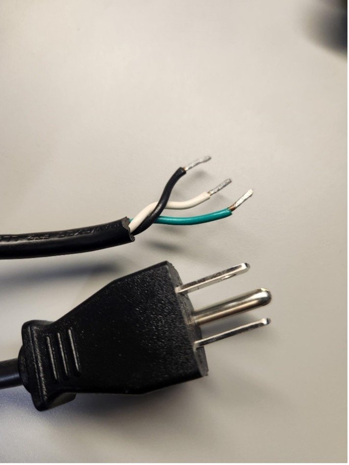
7) You can now install an input cable inside the enclosure. The cable can be lighter gauge since only the electronics are being powered up. On one end will be 3 bare wires and on the other can be a typical 3-prong residential plug. An example is a standard PC power cord with the PC side cut off. With the insulation removed, there will be 3 wires that can be stripped and the ends tinned (see picture below). Route the cable through the enclosure opening that the previous cable was in. Using the locations where you removed the large input cable, connect the bare wires to those terminals. The ground wire (green) is the first connection. Attach it to where the previous green wire was connected. The other two wires will be energized, so it does not matter which color connects to which of the remaining input power terminals. The picture below is an example of the cable end relative to the terminals.

Figure 7 - Example of a new input cable prepared for attachment

Figure 8 - Input cable attachment terminals in an Autel charger
8) With the wiring is complete, you can re-assemble the enclosure.
9) You can now plug the new input power cable into the 230V receptacle on the step-up transformer. We recommend securing the cable with zip ties to prevent accidental removal of the input cable.
Figure 9 - Input cable attached to the 230V port on the transformer
Conclusion
This shows you how to wire an EV charger for benchtop experimentation. The intent is to use an easy to get, cheap, pre-built cable that can be sacrificed to avoid having a researcher working with a limited budget attempt to build the high current and voltage infrastructure to their bench if they only intend to power up the electronics. If a researcher already has a 230VAC plug right next to their testbench, they will not need this modification. However, we suspect that most researchers just getting into the automotive space will not have these resources. That’s why we’re offering this work-around for those who don’t intend to connect to a vehicle and thus don’t need a high-current connection.
As always, we recommend using basic electrical safety handling procedures whenever working with electrical devices. Potentially lethal voltages will be present within the unit, especially when powered from a 230VAC source.
The modifications shown in this article should assist you in conveniently conducting your research into potential vulnerabilities in EV chargers. Our research has uncovered some already, and we continue looking into the attack surface of such devices. We hope you’re successful with your research, and if you discover a vulnerability, we hope you demonstrate it during the upcoming Pwn2Own Automotive contest.
Stay tuned to the blog for attack surface reviews and how-to guides for other devices, and if you’re curious, you can see all the devices included in the contest. Until then, follow the team on Twitter, Mastodon, LinkedIn, or Instagram for the latest in exploit techniques and security patches.
如有侵权请联系:admin#unsafe.sh