2022-2-17 18:25:41 Author: research.nccgroup.com(查看原文) 阅读量:72 收藏
Written by Catalin Visinescu
On November 3, 2021, Zero Day Initiative Pwn2Own announced that NCC Group EDG (Exploit Development Group) remotely exploited a vulnerability in the MC3224i printer firmware that offered full control over the device. Note that for Pwn2Own the printer was running the latest version of the firmware, CXLBL.075.272.
Listed as one of the targets of Austin 2021 Pwn2Own, the Lexmark MC3224i is a popular all-in-one color laser printer with great reviews on various sellers’ websites.
The vulnerability has now been addressed by Lexmark and the ZDI advisory available here. Part 2 will contain more information on the vulnerability and exploitation.
Lexmark encrypts the firmware update packages provided to consumers, making the binary analysis more difficult. With little over a month of research time assigned and few targets to look at, NCC Group decided to remove the flash memory and extract the firmware using a programmer, firmware which we (correctly) assumed would be stored unencrypted. This allowed us to bypass the firmware update package encryption. With the firmware extracted, the binaries could be reverse-engineered to find vulnerabilities that would allow remote code execution.
PCB overview
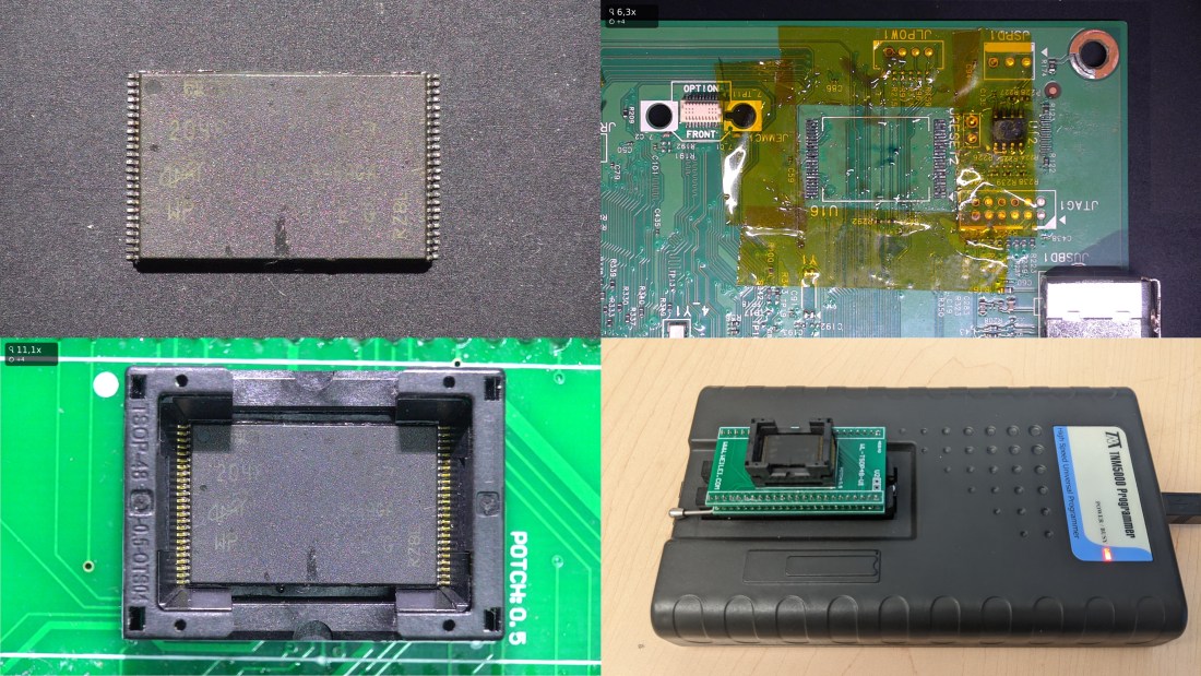
The main printed circuit board (PCB) is located on the left side of the printer. The device is powered by a Marvell 88PA6220-BUX2 System-on-Chip (SoC) which is specially designed for the printer industry and a Micron MT29F2G08ABAGA NAND flash (2Gb i.e. 256MB) for firmware storage. The NAND flash can be easily located on the lower left side of the PCB:

Serial output
The UART connector was quickly identified, which is labeled JRIP1 on the PCB:

Three wires were soldered with the intent to:
- review the boot log to understand the flash layout by observing the device’s partition information
- scan the boot log for any indications that software signature verification is performed by the printer
- hope to get a shell in either the bootloader (U-Boot) or the OS (Linux)
The serial output (115200 baud) of the printer’s boot process is shown below:
This file contains bidirectional Unicode text that may be interpreted or compiled differently than what appears below. To review, open the file in an editor that reveals hidden Unicode characters. Learn more about bidirectional Unicode characters
| Si Ge2-RevB 3.3.22-9h 12 14 25 | |
| TIME=Tue Mar 10 21:02:36 2020;COMMIT=863d60b | |
| uidc | |
| Failure Enabling AVS workaround on 88PG870 | |
| setting AVS Voltage to 1050 | |
| Bank5 Reg2 = 0x0000381E, VoltBin = 0, efuseEscape = 0 | |
| AVS efuse Values: | |
| Efuse Programed = 1 | |
| Low VDD Limit = 32 | |
| High VDD Limit = 32 | |
| Target DRO = 65535 | |
| Select Vsense0 = 0 | |
| a | |
| Calling Configure_Flashes @ 0xFFE010A8 12 FE 13 E0026800 | |
| fves | |
| DDR3 400MHz 1x16 4Gbit | |
| rSHA compare Passed 0 | |
| SHA compare Passed 0 | |
| l | |
| Launch AP Core0 @ 0x00100000 | |
| U-Boot 2018.07-AUTOINC+761a3261e9 (Feb 28 2020 - 23:26:43 +0000) | |
| DRAM: 512 MiB | |
| NAND: 256 MiB | |
| MMC: mv_sdh: 0, mv_sdh: 1, mv_sdh: 2 | |
| lxk_gen2_eeprom_probe:123: No panel eeprom option found. | |
| lxk_panel_notouch_probe_gen2:283: panel uicc type 68, hw vers 19, panel id 98, display type 11, firmware v4.5, lvds 4 | |
| found smpn display TM024HDH49 / ILI9341 default | |
| lcd_lvds_pll_init: Requesting dotclk=40000000Hz | |
| found smpn display Yeebo 2.8 B | |
| ubi0: default fastmap pool size: 100 | |
| ubi0: default fastmap WL pool size: 50 | |
| ubi0: attaching mtd1 | |
| ubi0: attached by fastmap | |
| ubi0: fastmap pool size: 100 | |
| ubi0: fastmap WL pool size: 50 | |
| ubi0: attached mtd1 (name "mtd=1", size 253 MiB) | |
| ubi0: PEB size: 131072 bytes (128 KiB), LEB size: 126976 bytes | |
| ubi0: min./max. I/O unit sizes: 2048/2048, sub-page size 2048 | |
| ubi0: VID header offset: 2048 (aligned 2048), data offset: 4096 | |
| ubi0: good PEBs: 2018, bad PEBs: 8, corrupted PEBs: 0 | |
| ubi0: user volume: 7, internal volumes: 1, max. volumes count: 128 | |
| ubi0: max/mean erase counter: 2/1, WL threshold: 4096, image sequence number: 0 | |
| ubi0: available PEBs: 0, total reserved PEBs: 2018, PEBs reserved for bad PEB handling: 32 | |
| Loading file '/shared/pm/softoff' to addr 0x1f6545d4... | |
| Unmounting UBIFS volume InternalStorage! | |
| Card did not respond to voltage select! | |
| bootcmd: setenv cramfsaddr 0x1e900000;ubi read 0x1e900000 Kernel 0xa67208;sha256verify 0x1e900000 0x1f367000 1;cramfsload 0x100000 /main.img;source 0x100000;loop.l 0xd0000000 1 | |
| Read 10908168 bytes from volume Kernel to 1e900000 | |
| Code authentication success | |
| ### CRAMFS load complete: 2165 bytes loaded to 0x100000 | |
| ## Executing script at 00100000 | |
| ### CRAMFS load complete: 4773416 bytes loaded to 0xa00000 | |
| ### CRAMFS load complete: 4331046 bytes loaded to 0x1600000 | |
| ## Booting kernel from Legacy Image at 00a00000 ... | |
| Image Name: Linux-4.17.19-yocto-standard-74b | |
| Image Type: ARM Linux Kernel Image (uncompressed) | |
| Data Size: 4773352 Bytes = 4.6 MiB | |
| Load Address: 00008000 | |
| Entry Point: 00008000 | |
| ## Loading init Ramdisk from Legacy Image at 01600000 ... | |
| Image Name: initramfs-image-granite2-2020063 | |
| Image Type: ARM Linux RAMDisk Image (uncompressed) | |
| Data Size: 4330982 Bytes = 4.1 MiB | |
| Load Address: 00000000 | |
| Entry Point: 00000000 | |
| ## Flattened Device Tree blob at 01500000 | |
| Booting using the fdt blob at 0x1500000 | |
| Loading Kernel Image ... OK | |
| Using Device Tree in place at 01500000, end 01516aff | |
| UPDATING DEVICE TREE WITH st:1fec4000 sz: 12c000 | |
| Starting kernel ... | |
| Booting Linux on physical CPU 0xffff00 | |
| Linux version 4.17.19-yocto-standard-74b7175b2a3452f756ffa76f750e50db ([email protected]) (gcc version 7.3.0 (GCC)) #1 SMP PREEMPT Mon Jun 29 19:46:01 UTC 2020 | |
| CPU: ARMv7 Processor [410fd034] revision 4 (ARMv7), cr=30c5383d | |
| CPU: div instructions available: patching division code | |
| CPU: PIPT / VIPT nonaliasing data cache, VIPT aliasing instruction cache | |
| OF: fdt: Machine model: mv6220 Lionfish 00d L | |
| earlycon: early_pxa0 at MMIO32 0x00000000d4030000 (options '') | |
| bootconsole [early_pxa0] enabled | |
| FIX ignoring exception 0xa11 addr=fb7ffffe swapper/0:1 | |
| ... |
On other devices NCC Group reviewed in the past, access to UART pins sometimes offered a full Linux shell. On the MC3224i the UART RX pin did not appear to be enabled, therefore we were only able to view the boot log, but not interact with the system. It may be possible that the pin is disabled through e-fuses on the SoC. Alternatively, a zero-ohm resistor may has been removed from the PCB on production devices, in which case it may be possible to re-enable it. Since our main goal was to remove the flash and extract the firmware, we did not investigate this further.
Dumping the firmware from the flash
Removing and dumping (or reprogramming) flash memory is a lot easier to accomplish than most people realize and the benefits are great: it often allows us to enable debug, obtain access to a shell, read sensitive keys, and in some cases bypass firmware signature verification. In our case though the goal was to extract the file system and to reverse-engineer the binaries as Pwn2Own rules clearly specified that only remotely executed exploits were acceptable. Still, there are no restrictions placed on the exploit development efforts. It is important to think of the development and execution of the exploit as separate efforts. While the execution effort dictates the scalability of an attack and cost to the attacker, the development effort (or NRE) need only be expended once for success, and so may reasonably consume sacrificial devices and a great deal of time without affecting the execution effort. It is the defender’s job to increase the execution effort.
Removing the flash was straightforward using a hot air rework station. After cleaning the pins we used a TNM5000 programmer with a TSOP-48 adapter to read the contents of the flash. We ensured the flash memory is properly seated in the adapter, selected the correct flash identifier and proceeded to reading the full content of the flash and saved it to a file. Re-attaching the flash needs to be done carefully to ensure a functional device. The entire process took about an hour, including testing the connections under a microscope. The printer booted successfully, hooray! The easy part was done…

The dumped flash image is exactly 285,212,672 bytes long, which is more than 268,435,456 bytes in 256MB. This is because the raw read of the flash includes spare areas, also referred to as page OOB (out-of-band) data areas. From the Micron spreadsheet:
> Internal ECC enables 9-bit detection and 8-bit correction in 528 bytes (x8) of main area
> and 16 bytes (x8) of spare area. […]
> During a PROGRAM operation, the device calculates an ECC code on the 2k page in the
> cache register, before the page is written to the NAND Flash array. The ECC code is stored
> in the spare area of the page.
> During a READ operation, the page data is read from the array to the cache register,
> where the ECC code is calculated and compared with the ECC code value read from the
> array. If a 1- to 8-bit error is detected, the error is corrected in the cache register. Only
> corrected data is output on the I/O bus.
The NAND flash memory is programmed and read using a page-based granularity. A page is made up of 2048 bytes of usable storage space and 128 bytes of OOB used to store the error correction codes and flags for bad block management, for a total of 2,176 bytes.
The erase operation has block-based granularity. According to the Micron’s documentation, for this flash part one block is made up of 64 pages, for a total of 128KB usable data.
The flash has two planes, each containing 1024 blocks. Putting everything together:
2 planes * 1024 blocks/plane * 64 pages/block * (2048 + 128) bytes/page = 285,212,672
Since the spare area is only required for flash-management use and does not contains useful user data, we wrote a small script that drops the 128 bytes of OOB data after each 2048-byte page. The resulting file is exactly 256MB.
Extracting the Marvell images
Remember we said the printer is powered by a Marvell chipset? This is when that information comes handy. While the 88PA6220 was specially designed for the printer industry, the firmware image format looks to be identical to that of other Marvell SoCs. As such there are many documents from similar processors or code on GitHub that can be used as reference. For instance we see that the image starts with a TIM (Trusted Image Module) header. The header contains a great deal of information about other images, some of which was used to extract the individual images as we shall see in this section of the blog:

The TIM header format is presented below in the last structure (obviously, it assumes the OOB data has already been removed):
This file contains bidirectional Unicode text that may be interpreted or compiled differently than what appears below. To review, open the file in an editor that reveals hidden Unicode characters. Learn more about bidirectional Unicode characters
| typedef struct { | |
| unsigned int Version; | |
| unsigned int Identifier; | |
| unsigned int Trusted; | |
| unsigned int IssueDate; | |
| unsigned int OEMUniqueID; | |
| } VERSION_I; | |
| typedef struct { | |
| unsigned int Reserved[5]; | |
| unsigned int BootFlashSign; | |
| } FLASH_I, *pFLASH_I; | |
| // Constant part of the header | |
| typedef struct { | |
| { | |
| VERSION_I VersionBind; | |
| FLASH_I FlashInfo; | |
| unsigned int NumImages; | |
| unsigned int NumKeys; | |
| unsigned int SizeOfReserved; | |
| } CTIM, *pCTIM; | |
| typedef struct { | |
| uint32_t ImageID; // Indicate which Image | |
| uint32_t NextImageID; // Indicate next image in the chain | |
| uint32_t FlashEntryAddr; // Block numbers for NAND | |
| uint32_t LoadAddr; | |
| uint32_t ImageSize; | |
| uint32_t ImageSizeToHash; | |
| HASHALGORITHMID_T HashAlgorithmID; // See HASHALGORITHMID_T | |
| uint32_t Hash[16]; // Reserve 512 bits for the hash | |
| uint32_t PartitionNumber; | |
| } IMAGE_INFO_3_4_0, *pIMAGE_INFO_3_4_0; // 0x60 bytes | |
| typedef struct { | |
| unsigned intKeyID; | |
| unsigned int HashAlgorithmID; | |
| unsigned int ModulusSize; | |
| unsigned int PublicKeySize; | |
| unsigned int RSAPublicExponent[64]; | |
| unsigned int RSAModulus[64]; | |
| unsigned int KeyHash[8]; | |
| } KEY_MOD, *pKEY_MOD; | |
| typedef struct { | |
| pCTIM pConsTIM; // Constant part | |
| pIMAGE_INFO pImg; // Pointer to Images (v 3.4.0) | |
| pKEY_MOD pKey; // Pointer to Keys | |
| unsigned int *pReserved; // Pointer to Reserved Area | |
| pPLAT_DS pTBTIM_DS; // Pointer to Digital Signature | |
| } TIM; |
As detailed below, the processor was secured by the Lexmark team, so let’s take a look at some of the relevant fields that help us extract the images. For a complete description of each field please refer to this Reference Manual:
VERSION_I– general TIM header informations.Version(0x00030400) – TIM header version (3.4.0). This is useful later to identify which version of Image Info structure (IMAGE_INFO_3_4_0) is used.Identifier(0x54494D48) – always ASCII "TIMH", a constant string used to identify a valid header.Trusted(0x00000001) – 0 for insecure processors, 1 for secure. The processor has been secured by Lexmark therefore only signed firmware is allowed to run on these devices.
FLASH_I– boot flash properties.NumImages(0x00000004) – indicates there are four structures in the header that describe images making up the firmware.NumKeys(0x00000001) – one key information structure is present in this header.SizeOfReserved(0x00000000) – just before the signature at the end of the TIM header, the OEM can reserve up to 4KB – sizeof(TIMH) for their use. Lexmark is not using this feature.IMAGE_INFO_3_4_0– image 1 information.ImageID(0x54494D48) – id of image ("TIMH"), TIM header in this case.NextImageID(0x4F424D49) – id of following image ("OBMI"), OEM Boot Module Image.FlashEntryAddr(0x00000000) – index in flash memory where the TIM header is located.ImageSize(0x00000738) – the size of the image, 1,848 bytes for the header.
IMAGE_INFO_3_4_0– image 2 information.ImageID(0x4F424D49) – id of image ("OBMI"), OEM Boot Module Image. Provided by Marvell, the OBM is responsible for tasks needed to boot the printer. Looking at the UART boot log, everything that displayed before the U-Boot start message is displayed by the OBM code. As for functionality, the OBM sets up DDR and the Application Processor Core 0 and performs firmware signature verification of the firmware loaded subsequently (U-Boot).NextImageID(0x4F534C4F) – id of following image ("OSLO").FlashEntryAddr(0x00001000) – index in flash memory where OBMI is located.ImageSize(0x0000FD40) – the size of the image, 64,832 bytes for OBMI.
IMAGE_INFO_3_4_0– image 3 information.ImageID(0x4F534C4F) – id of image ("OSLO"), contains U-Boot code.NextImageID(0x54524458) – id of following image ("TRDX").FlashEntryAddr(0x000C0000) – index in flash memory where OSLO image is located.ImageSize(0x000712FF) – the size of the image, 463,615 bytes for OSLO.
IMAGE_INFO_3_4_0– image 4 information.ImageID(0x54524458) – id of image ("TRDX"), contains Linux kernel and device tree image (likely used for recovery).NextImageID(0xFFFFFFFF) – id of following image, this value signals no more images are following.FlashEntryAddr(0x00132000) – index in flash memory where TRDX image is located.ImageSize(0x000E8838) – the size of the image, 952,376 bytes for TRDX.
Of course, these Marvell images make up only a small fraction of the flash size. Looking past these images we have recognized the UBI erase block signature "UBI#" showing up every 131,072 bytes, i.e. 128KB, i.e. every flash block (1 block * 64 pages/block * 2048-bytes/page). In total we shall see that there were 2,024 UBI blocks resulting in a file (we named it ubi_data.bin) that is 253MB in size.
$ file ubi_data.bin
ubi_data.bin: UBI image, version 1
We expect this file to contain the interesting material we are after.
Extracting the UBI volumes
Ok, so we have an UBI image (named ubi_data.bin) that contains all the UBI blocks:
What now? First a bit more about UBI…
The first four bytes of the first page of each erase block starts with "UBI#", as mentioned above. This shows that the first page is occupied by the erase count header which contains stats used for wear-protection operations. If the block contains user data, the second page in the block is occupied by the volume header (starts with "UBI!"). As the first two pages of each block contain metadata, only 62 of the 64 pages (124KB) store user data, a little less than the expected 128KB.
Let’s see what’s inside using the ubi_read tool:
- 2024 erase blocks
- 1302 blocks used for data (part of a volume), represents the block count sum for all volumes
- seven volumes: Kernel, Base, Copyright, Engine, InternalStorage, MBR, ManBlock
$ ubireader_display_info ubi_data.bin
UBI File
---------------------
	Min I/O: 2048
	LEB Size: 126976
	PEB Size: 131072
	Total Block Count: 2024
	Data Block Count: 1302
	Layout Block Count: 2
	Internal Volume Block Count: 1
	Unknown Block Count: 719
	First UBI PEB Number: 2.0

	Image: 0
	---------------------
		Image Sequence Num: 0
		Volume Name:Kernel
		Volume Name:Base
		Volume Name:Copyright
		Volume Name:Engine
		Volume Name:InternalStorage
		Volume Name:MBR
		Volume Name:ManBlock
		PEB Range: 0 - 2023

		Volume: Kernel
		---------------------
			Vol ID: 2
			Name: Kernel
			Block Count: 95

			Volume Record
			---------------------
				alignment: 1
				crc: '0x8abc33f6'
				data_pad: 0
				errors: ''
				flags: 0
				name: 'Kernel'
				name_len: 6
				padding: '\x00\x00\x00\x00\x00\x00\x00\x00\x00\x00\x00\x00\x00\x00\x00\x00\x00\x00\x00\x00\x00\x00\x00'
				rec_index: 2
				reserved_pebs: 133
				upd_marker: 0
				vol_type: 'dynamic'

		Volume: Base
		---------------------
			Vol ID: 3
			Name: Base
			Block Count: 927

			Volume Record
			---------------------
				alignment: 1
				crc: '0xc3f30751'
				data_pad: 0
				errors: ''
				flags: 0
				name: 'Base'
				name_len: 4
				padding: '\x00\x00\x00\x00\x00\x00\x00\x00\x00\x00\x00\x00\x00\x00\x00\x00\x00\x00\x00\x00\x00\x00\x00'
				rec_index: 3
				reserved_pebs: 1132
				upd_marker: 0
				vol_type: 'dynamic'

		Volume: Copyright
		---------------------
			Vol ID: 4
			Name: Copyright
			Block Count: 1

			Volume Record
			---------------------
				alignment: 1
				crc: '0xa065ca'
				data_pad: 0
				errors: ''
				flags: 0
				name: 'Copyright'
				name_len: 9
				padding: '\x00\x00\x00\x00\x00\x00\x00\x00\x00\x00\x00\x00\x00\x00\x00\x00\x00\x00\x00\x00\x00\x00\x00'
				rec_index: 4
				reserved_pebs: 3
				upd_marker: 0
				vol_type: 'dynamic'

		Volume: Engine
		---------------------
			Vol ID: 15
			Name: Engine
			Block Count: 21

			Volume Record
			---------------------
				alignment: 1
				crc: '0x66c80b4b'
				data_pad: 0
				errors: ''
				flags: 0
				name: 'Engine'
				name_len: 6
				padding: '\x00\x00\x00\x00\x00\x00\x00\x00\x00\x00\x00\x00\x00\x00\x00\x00\x00\x00\x00\x00\x00\x00\x00'
				rec_index: 15
				reserved_pebs: 34
				upd_marker: 0
				vol_type: 'dynamic'

		Volume: InternalStorage
		---------------------
			Vol ID: 24
			Name: InternalStorage
			Block Count: 256

			Volume Record
			---------------------
				alignment: 1
				crc: '0x962ca517'
				data_pad: 0
				errors: ''
				flags: 0
				name: 'InternalStorage'
				name_len: 15
				padding: '\x00\x00\x00\x00\x00\x00\x00\x00\x00\x00\x00\x00\x00\x00\x00\x00\x00\x00\x00\x00\x00\x00\x00'
				rec_index: 24
				reserved_pebs: 674
				upd_marker: 0
				vol_type: 'dynamic'

		Volume: MBR
		---------------------
			Vol ID: 90
			Name: MBR
			Block Count: 1

			Volume Record
			---------------------
				alignment: 1
				crc: '0x5fee82ff'
				data_pad: 0
				errors: ''
				flags: 0
				name: 'MBR'
				name_len: 3
				padding: '\x00\x00\x00\x00\x00\x00\x00\x00\x00\x00\x00\x00\x00\x00\x00\x00\x00\x00\x00\x00\x00\x00\x00'
				rec_index: 90
				reserved_pebs: 2
				upd_marker: 0
				vol_type: 'static'

		Volume: ManBlock
		---------------------
			Vol ID: 91
			Name: ManBlock
			Block Count: 1

			Volume Record
			---------------------
				alignment: 1
				crc: '0x28cd6521'
				data_pad: 0
				errors: ''
				flags: 0
				name: 'ManBlock'
				name_len: 8
				padding: '\x00\x00\x00\x00\x00\x00\x00\x00\x00\x00\x00\x00\x00\x00\x00\x00\x00\x00\x00\x00\x00\x00\x00'
				rec_index: 91
				reserved_pebs: 2
				upd_marker: 0
				vol_type: 'static'
Ok, now to extract the seven volumes mentioned above in the ubi_data_bin_extracted folder:
$ ubireader_extract_images ubi_data.bin -v -o ubi_data_bin_extracted
$ ls -lh ubi_data_bin_extracted/ubi_data.bin/
-rw-rw-r-- 1 cvisinescu cvisinescu 113M Jan 17 19:10 img-0_vol-Base.ubifs
-rw-rw-r-- 1 cvisinescu cvisinescu 124K Jan 17 19:10 img-0_vol-Copyright.ubifs
-rw-rw-r-- 1 cvisinescu cvisinescu 2.6M Jan 17 19:10 img-0_vol-Engine.ubifs
-rw-rw-r-- 1 cvisinescu cvisinescu  49M Jan 17 19:10 img-0_vol-InternalStorage.ubifs
-rw-rw-r-- 1 cvisinescu cvisinescu  12M Jan 17 19:10 img-0_vol-Kernel.ubifs
-rw-rw-r-- 1 cvisinescu cvisinescu 124K Jan 17 19:10 img-0_vol-ManBlock.ubifs
-rw-rw-r-- 1 cvisinescu cvisinescu 124K Jan 17 19:10 img-0_vol-MBR.ubifs
The volumes represent partitions used by the device, some of which are file systems:
$ file *.ubifs
img-0_vol-Base.ubifs:            Squashfs filesystem, little endian, version 1024.0, compressed, 4280940851934265344 bytes, -1506476032 inodes, blocksize: 512 bytes, created: Sun Nov  5 14:27:44 2034
img-0_vol-Copyright.ubifs:       data
img-0_vol-Engine.ubifs:          Squashfs filesystem, little endian, version 1024.0, compressed, 7678397671131840512 bytes, 1610612736 inodes, blocksize: 512 bytes, created: Sat Nov 14 21:23:44 2026
img-0_vol-InternalStorage.ubifs: UBIfs image, sequence number 1, length 4096, CRC 0x44d52349
img-0_vol-Kernel.ubifs:          Linux Compressed ROM File System data, little endian size 11939840 version #2 sorted_dirs CRC 0x35eb963f, edition 0, 4424 blocks, 191 files
img-0_vol-ManBlock.ubifs:        data
img-0_vol-MBR.ubifs:             DOS/MBR boot sector; partition 1 : ID=0xff, active 0xff, start-CHS (0x3ff,255,63), end-CHS (0x3ff,255,63), startsector 4294967295, 4294967295 sectors; partition 2 : ID=0xff, active 0xff, start-CHS (0x3ff,255,63), end-CHS (0x3ff,255,63), startsector 4294967295, 4294967295 sectors; partition 3 : ID=0xff, active 0xff, start-CHS (0x3ff,255,63), end-CHS (0x3ff,255,63), startsector 4294967295, 4294967295 sectors; partition 4 : ID=0xff, active 0xff, start-CHS (0x3ff,255,63), end-CHS (0x3ff,255,63), startsector 4294967295, 65535 sectors
Accessing the user data (writable partition)
This section describes how to mount img-0_vol-InternalStorage.ubifs which is a UBIFS image. To do so, a number of steps must be performed.
We will first need to load the NAND flash simulator kernel module. This module uses RAM to imitate physical NAND flash devices. Check for the appearance of /dev/mtd0 and /dev/mtd0ro and the output of dmesg on the Linux machine after running the following command. The four bytes represent the values returned by the READ ID flash command (0x90), but also available in the Micron NAND flash datasheet in the "Read ID Parameters for Address 00h" table:
$ sudo modprobe nandsim first_id_byte=0x2C second_id_byte=0xDA third_id_byte=0x90 fourth_id_byte=0x95
$ ls -l /dev/mtd*
The simulated NAND flash is 256MB and each erase block is 128KB, which matches the physical flash. Since we are only mounting one volume of 49MB, space should not be a problem:
$ cat /proc/mtd
dev:    size   erasesize  name
mtd0: 10000000 00020000 "NAND simulator partition 0"
$ dmesg | grep "nand:"
[50027.712675] nand: device found, Manufacturer ID: 0x2c, Chip ID: 0xda
[50027.712677] nand: Micron NAND 256MiB 3,3V 8-bit
[50027.712678] nand: 256 MiB, SLC, erase size: 128 KiB, page size: 2048, OOB size: 64
Note that the OOB size reported by dmesg is 64 bytes which is incorrect, since it should have been 128 bytes. However, since we are simulating the NAND flash in RAM this is not an issue. At the time of this writing nandsim does not support the model of Micron NAND flash used by the printer.
Next, let us erase all the blocks from start to end. For more details run flash_erase --help:
$ sudo flash_erase /dev/mtd0 0 0
Erasing 128 Kibyte @ ffe0000 -- 100 % complete
With all simulated NAND flash blocks erased, let’s format the partition. The first parameter specifies the minimum input/output unit, in our case one page. The second specifies offset of the volume id, in our case 2048 bytes into the UBI erase block, as presented earlier in this section of the blog.
$ sudo ubiformat /dev/mtd0 -s 2048 -O 2048
ubiformat: mtd0 (nand), size 268435456 bytes (256.0 MiB), 2048 eraseblocks of 131072 bytes (128.0 KiB), min. I/O size 2048 bytes
libscan: scanning eraseblock 2047 -- 100 % complete
ubiformat: 2048 eraseblocks are supposedly empty
ubiformat: formatting eraseblock 2047 -- 100 % complete
There is one more kernel module we need to load:
$ sudo modprobe ubi
$ ls -l /dev/ubi_ctrl
The following command attaches /dev/mtd0 to UBI. The first parameter indicates which MTD device (i.e. /dev/mtd0) is used. The second indicates the UBI device to be created (i.e. /dev/ubi0), which is used to access the UBI volume. The third parameter specifies again the offset of the volume id.
$ sudo ubiattach -m 0 -d 0 -O 2048
UBI device number 0, total 2048 LEBs (260046848 bytes, 248.0 MiB), available 2002 LEBs (254205952 bytes, 242.4 MiB), LEB size 126976 bytes (124.0 KiB)
$ ls -l /dev/ubi0
Now we create a volume which we will name my_volume_InternalStorage and access via /dev/ubi0_0 (first volume on device). The command below allocating a volume equal to the size of the partition fails because, as mentioned earlier, two pages per erase block are used for the UBI and volume headers. As such, for each 128KB UBI erase block 4KB are lost. We can however create a volume that is 240MB (i.e. 1982 erase blocks * 124 KB/erase block), much larger than our img-0_vol-InternalStorage.ubifs volume which is 49MB:
$ sudo ubimkvol /dev/ubi0 -N my_volume_InternalStorage -s 256MiB
ubimkvol: error!: cannot UBI create volume
          error 28 (No space left on device)

$ sudo ubimkvol /dev/ubi0 -N my_volume_InternalStorage -s 240MiB
Volume ID 0, size 1982 LEBs (251666432 bytes, 240.0 MiB), LEB size 126976 bytes (124.0 KiB), dynamic, name "my_volume_InternalStorage", alignment 1
$ ls -l /dev/ubi0_0
Additional information about the UBI device can be obtained using ubinfo /dev/ubi0 and ubinfo /dev/ubi0_0. Now to put the extracted volume image in the UBI device 0 and volume 0:
$ ubiupdatevol /dev/ubi0_0 img-0_vol-InternalStorage.ubifs
Finally, we can mount the UBI device using the mount command below. Alternatively, sudo mount -t ubifs ubi0:my_volume_InternalStorage mnt/ can also be used:
$ mkdir mnt
$ sudo mount -t ubifs ubi0_0 mnt/
$ ls -l mnt/
drwxr-xr-x  2 root root  160 Mar  2  2020 bookmarkmgr
drwxr-xr-x  2 root root  232 Mar  2  2020 http
drwxr-xr-x  2 root root  400 Sep 10 15:21 iq
drwxr-xr-x  2 root root  160 Mar  2  2020 log
drwxr-xr-x  2 root root  160 Mar  2  2020 nv2
-rw-r--r--  1 root root    0 Mar  2  2020 sb-dbg
drwxr-xr-x  6 root root  424 Mar  2  2020 security
drwxr-xr-x 41 root root 2816 Mar 16  2021 shared
drwxr-xr-x  2 root root  224 Mar  2  2020 thinscan
In this file system we find data such as the following:
- auth database, contains user account from when we first set up the printer (username and hash of password)
- some public and encrypted private certificates
- calibration data
To undo everything, we run the following commands:
$ sudo umount mnt/
$ sudo ubirmvol /dev/ubi0 -n 0
$ sudo ubidetach -m 0
$ sudo modprobe -r ubifs
$ sudo modprobe -r ubi
$ sudo modprobe -r nandsim
Accessing the printer binaries (read-only partition)
This section describes how to extract the content of img-0_vol-Base.ubifs which we found it holds the binaries most interesting for us to reverse engineer:
$ unsquashfs img-0_vol-Base.ubifs
$ ls -l Base_squashfs_dir
drwxr-xr-x  2 cvisinescu cvisinescu 4096 Jun 22  2021 bin
drwxr-xr-x  2 cvisinescu cvisinescu 4096 Jun 22  2021 boot
-rw-r--r--  1 cvisinescu cvisinescu  909 Jun 22  2021 Build.Info
drwxr-xr-x  2 cvisinescu cvisinescu 4096 Mar 11  2021 dev
drwxr-xr-x 53 cvisinescu cvisinescu 4096 Jun 22  2021 etc
drwxr-xr-x  6 cvisinescu cvisinescu 4096 Jun 22  2021 home
drwxr-xr-x  8 cvisinescu cvisinescu 4096 Jun 22  2021 lib
drwxr-xr-x  2 cvisinescu cvisinescu 4096 Mar 11  2021 media
drwxr-xr-x  2 cvisinescu cvisinescu 4096 Mar 11  2021 mnt
drwxr-xr-x  5 cvisinescu cvisinescu 4096 Jun 22  2021 opt
drwxr-xr-x  2 cvisinescu cvisinescu 4096 Jun 22  2021 pkg-netapps
dr-xr-xr-x  2 cvisinescu cvisinescu 4096 Mar 11  2021 proc
drwx------  4 cvisinescu cvisinescu 4096 Jun 22  2021 root
drwxr-xr-x  2 cvisinescu cvisinescu 4096 Mar 11  2021 run
drwxr-xr-x  2 cvisinescu cvisinescu 4096 Jun 22  2021 sbin
drwxr-xr-x  2 cvisinescu cvisinescu 4096 Mar 11  2021 srv
dr-xr-xr-x  2 cvisinescu cvisinescu 4096 Mar 11  2021 sys
drwxrwxrwt  2 cvisinescu cvisinescu 4096 Mar 11  2021 tmp
drwxr-xr-x 10 cvisinescu cvisinescu 4096 Apr 18  2021 usr
drwxr-xr-x 13 cvisinescu cvisinescu 4096 Mar 16  2021 var
lrwxrwxrwx  1 cvisinescu cvisinescu   14 Jun 14  2021 web -> /usr/share/web
Success… now that we have the binaries, we can begin the task of reverse engineering them and understand how the printer works: vulnerabilities included. Part 2 of this blog will further show the reader the process used to finally compromise the printer.
In summary, the image on the NAND flash memory looks as follows:
- TIMH – Trusted Image Module header, Marvell-specific
- OBMI – first bootloader, written by Marvell
- OSLO – second bootloader (U-Boot)
- TRDX – Linux kernel and device tree
- UBI image
- Base – squashfs filesystem for binaries
- Copyright – raw data
- Engine – squashfs filesystem contains some kernel modules for motors, belt, fan, etc.
- InternalStorage – UBI FS image for user data (writable)
- Kernel – compressed Linux kernel
- ManBlock – raw data, empty partititon
- MBR – Master Boot Record, contains information about partitions: Base, Copyright, Engine, InternalStorage and Kernel
During the early days of the project we first tried to modify parts of the firmware image (including the error correction code in the spare areas). The end goal was to perform dynamic testing on a live system and eventually obtain a shell which we could use to dump the binaries, view running processes, review file permissions, and understand how the Lexmark firmware works in general. It required repeated programming of the flash. While we can reliably re-attach the flash on the PCB multiple times, each attempt carries a risk of damage to both the chip and the PCB pads on which it is mounted.
Ordering replacement flash parts from the common vendors was not an option due to chip shortages. As such we attempted to create a contraption that would help us use the TSOP-48 adapter directly, basically a poor man’s chip socket.

The connections were good, but the device would not boot past U-Boot (as observed over serial) for reasons we did not understand:
This file contains bidirectional Unicode text that may be interpreted or compiled differently than what appears below. To review, open the file in an editor that reveals hidden Unicode characters. Learn more about bidirectional Unicode characters
| Si Ge2-RevB 3.3.22-9h 12 14 25 | |
| TIME=Tue Jun 08 20:32:27 2021;COMMIT=863d60b | |
| uidc | |
| Failure Enabling AVS workaround on 88PG870 | |
| setting AVS Voltage to 1050 | |
| Bank5 Reg2 = 0x000038E4, VoltBin = 0, efuseEscape = 0 | |
| AVS efuse Values: | |
| Efuse Programed = 1 | |
| Low VDD Limit = 31 | |
| High VDD Limit = 31 | |
| Target DRO = 65535 | |
| Select Vsense0 = 0 | |
| a | |
| Calling Configure_Flashes @ 0xFFE010A8 12 FE 13 E0026800 | |
| fves | |
| DDR3 400MHz 1x16 4Gbit | |
| rSHA compare Passed 0 | |
| SHA compare Passed 0 | |
| l | |
| Launch AP Core0 @ 0x00100000 | |
| U-Boot 2018.07-AUTOINC+761a3261e9 (Jun 08 2021 - 20:32:14 +0000) | |
| DRAM: 512 MiB | |
| NAND: 256 MiB | |
| MMC: mv_sdh: 0, mv_sdh: 1, mv_sdh: 2 | |
| lxk_gen2_eeprom_probe:123: No panel eeprom option found. | |
| lxk_panel_notouch_probe_gen2:283: panel uicc type 68, hw vers 19, panel id 98, display type 11, firmware v4.5, lvds 4 | |
| found smpn display TM024HDH49 / ILI9341 default | |
| lcd_lvds_pll_init: Requesting dotclk=40000000Hz | |
| found smpn display Yeebo 2.8 B | |
| ubi0: default fastmap pool size: 100 | |
| ubi0: default fastmap WL pool size: 50 | |
| ubi0: attaching mtd1 | |
| ubi0: attached by fastmap | |
| ubi0: fastmap pool size: 100 | |
| ubi0: fastmap WL pool size: 50 | |
| ubi0: attached mtd1 (name "mtd=1", size 253 MiB) | |
| ubi0: PEB size: 131072 bytes (128 KiB), LEB size: 126976 bytes | |
| ubi0: min./max. I/O unit sizes: 2048/2048, sub-page size 2048 | |
| ubi0: VID header offset: 2048 (aligned 2048), data offset: 4096 | |
| ubi0: good PEBs: 2018, bad PEBs: 8, corrupted PEBs: 0 | |
| ubi0: user volume: 7, internal volumes: 1, max. volumes count: 128 | |
| ubi0: max/mean erase counter: 4/2, WL threshold: 4096, image sequence number: 0 | |
| ubi0: available PEBs: 0, total reserved PEBs: 2018, PEBs reserved for bad PEB handling: 32 | |
| Loading file '/shared/pm/softoff' to addr 0x1f6545d4... | |
| Unmounting UBIFS volume InternalStorage! | |
| Card did not respond to voltage select! | |
| bootcmd: setenv cramfsaddr 0x1e800000;ubi read 0x1e800000 Kernel 0xb63208;sha256verify 0x1e800000 0x1f363000 1;cramfsload 0x100000 /main.img;source 0x100000;loop.l 0xd0000000 1 | |
| Read 11940360 bytes from volume Kernel to 1e800000 | |
| Code authentication success | |
| ### CRAMFS load complete: 2165 bytes loaded to 0x100000 | |
| ## Executing script at 00100000 | |
| ### CRAMFS load complete: 4773552 bytes loaded to 0xa00000 | |
| ### CRAMFS load complete: 5123782 bytes loaded to 0x1600000 | |
| ## Booting kernel from Legacy Image at 00a00000 ... | |
| Image Name: Linux-4.17.19-yocto-standard-2f4 | |
| Image Type: ARM Linux Kernel Image (uncompressed) | |
| Data Size: 4773488 Bytes = 4.6 MiB | |
| Load Address: 00008000 | |
| Entry Point: 00008000 | |
| ## Loading init Ramdisk from Legacy Image at 01600000 ... | |
| Image Name: initramfs-image-granite2-2021061 | |
| Image Type: ARM Linux RAMDisk Image (uncompressed) | |
| Data Size: 5123718 Bytes = 4.9 MiB | |
| Load Address: 00000000 | |
| Entry Point: 00000000 | |
| ## Flattened Device Tree blob at 01500000 | |
| Booting using the fdt blob at 0x1500000 | |
| Loading Kernel Image ... OK | |
| Using Device Tree in place at 01500000, end 01516b28 | |
| UPDATING DEVICE TREE WITH st:1fec4000 sz: 12c000 | |
| Starting kernel ... | |
| Booting Linux on physical CPU 0xffff00 | |
| Linux version 4.17.19-yocto-standard-2f4d6903b333a60c46f1f33da4b122d1 ([email protected]) (gcc version 7.3.0 (GCC)) #1 SMP PREEMPT Thu Jun 10 20:19:42 UTC 2021 | |
| CPU: ARMv7 Processor [410fd034] revision 4 (ARMv7), cr=30c5383d | |
| CPU: div instructions available: patching division code | |
| CPU: PIPT / VIPT nonaliasing data cache, VIPT aliasing instruction cache | |
| OF: fdt: Machine model: mv6220 Lionfish 00d L | |
| earlycon: early_pxa0 at MMIO32 0x00000000d4030000 (options '') | |
| bootconsole [early_pxa0] enabled | |
| FIX ignoring exception 0xa11 addr=a7ff7dfe swapper/0:1 | |
| starting version 237 | |
| mount: mounting /dev/active-partitions/Base on /newrootfs failed: No such file or directory | |
| Unknown device, --name=, --path=, or absolute path in /dev/ or /sys expected. | |
| mount: mounting /dev/active-partitions/Base on /newrootfs failed: No such file or directory | |
| mount: mounting /dev/active-partitions/Base on /newrootfs failed: No such file or directory | |
| mount: mounting /dev on /newrootfs/dev failed: No such file or directory | |
| mount: mounting /tmp on /newrootfs/var failed: No such file or directory | |
| ln: /newrootfs/var/dev: No such file or directory | |
| BusyBox v1.27.2 (2021-03-11 21:59:45 UTC) multi-call binary. | |
| Usage: switch_root [-c /dev/console] NEW_ROOT NEW_INIT [ARGS] | |
| Free initramfs and switch to another root fs: | |
| chroot to NEW_ROOT, delete all in /, move NEW_ROOT to /, | |
| execute NEW_INIT. PID must be 1. NEW_ROOT must be a mountpoint. | |
| -c DEV Reopen stdio to DEV after switch | |
| Kernel panic - not syncing: Attempted to kill init! exitcode=0x00000100 | |
| CPU: 1 PID: 1 Comm: switch_root Tainted: P O 4.17.19-yocto-standard-2f4d6903b333a60c46f1f33da4b122d1 #1 | |
| Hardware name: Marvell Pegmatite (Device Tree) | |
| [<c001b3fc>] (unwind_backtrace) from [<c0015b7c>] (show_stack+0x20/0x24) | |
| [<c0015b7c>] (show_stack) from [<c0637468>] (dump_stack+0x78/0x94) | |
| [<c0637468>] (dump_stack) from [<c002f238>] (panic+0xe8/0x27c) | |
| [<c002f238>] (panic) from [<c0034314>] (do_exit+0x61c/0xa6c) | |
| [<c0034314>] (do_exit) from [<c0034818>] (do_group_exit+0x68/0xd0) | |
| [<c0034818>] (do_group_exit) from [<c00348a0>] (__wake_up_parent+0x0/0x30) | |
| [<c00348a0>] (__wake_up_parent) from [<c0009000>] (ret_fast_syscall+0x0/0x50) | |
| Exception stack(0xd2e2dfa8 to 0xd2e2dff0) | |
| dfa0: 480faba0 480faba0 00000001 00000000 00000001 00000001 | |
| dfc0: 480faba0 480faba0 00000000 000000f8 00000001 00000000 480ff780 480fc4d0 | |
| dfe0: 47faf908 beaa2b74 47fee90c 4805aac4 | |
| pegmatite_wdt: set TTCR: 15000 | |
| pegmatite_wdt: set APS_TMR_WMR: 6912 | |
| CPU0: stopping | |
| CPU: 0 PID: 0 Comm: swapper/0 Tainted: P O 4.17.19-yocto-standard-2f4d6903b333a60c46f1f33da4b122d1 #1 | |
| Hardware name: Marvell Pegmatite (Device Tree) | |
| [<c001b3fc>] (unwind_backtrace) from [<c0015b7c>] (show_stack+0x20/0x24) | |
| [<c0015b7c>] (show_stack) from [<c0637468>] (dump_stack+0x78/0x94) | |
| [<c0637468>] (dump_stack) from [<c001913c>] (handle_IPI+0x230/0x338) | |
| [<c001913c>] (handle_IPI) from [<c000a218>] (gic_handle_irq+0xe4/0xfc) | |
| [<c000a218>] (gic_handle_irq) from [<c00099f8>] (__irq_svc+0x58/0x8c) | |
| Exception stack(0xc0999e68 to 0xc0999eb0) | |
| 9e60: 00000000 c09f70a4 00000001 00000050 c09f70a4 c09f6f14 | |
| 9e80: 00000005 c0a09cb4 dfe16598 00000005 00000005 c0999f04 c0999eb8 c0999eb8 | |
| 9ea0: c0503684 c0503690 60000113 ffffffff | |
| [<c00099f8>] (__irq_svc) from [<c0503690>] (cpuidle_enter_state+0x2bc/0x3a8) | |
| [<c0503690>] (cpuidle_enter_state) from [<c05037f0>] (cpuidle_enter+0x48/0x4c) | |
| [<c05037f0>] (cpuidle_enter) from [<c005f0e4>] (call_cpuidle+0x44/0x48) | |
| [<c005f0e4>] (call_cpuidle) from [<c005f4a0>] (do_idle+0x1e0/0x270) | |
| [<c005f4a0>] (do_idle) from [<c005f7f8>] (cpu_startup_entry+0x28/0x30) | |
| [<c005f7f8>] (cpu_startup_entry) from [<c064bd54>] (rest_init+0xc0/0xe0) | |
| [<c064bd54>] (rest_init) from [<c0913f40>] (start_kernel+0x418/0x4bc) | |
| ---[ end Kernel panic - not syncing: Attempted to kill init! exitcode=0x00000100 ]--- |
The signal integrity due to cable length was a concern and we tried to use a shorter cable, unfortunately with the same results.

At this point the return on investment for the time spent was low, so we decided to better invest the time on reversing the binaries. Turned out it was a good idea as we will see in the second part of this blog coming soon.
如有侵权请联系:admin#unsafe.sh