1、黑客破解starlink路由器一代固件提取及分析
2、黑客破解starlink路由器二代固件提取及分析
3、黑客破解starlink路由器地面站固件提取及分析
4、黑客疯狂对starlink地面站和路由器暴力拆解
5、参考链接
现在草民我把这两篇文章给大家翻译以下贴出来分享给大家,便于大家了解星链用户端地面站和无线路由器的详细设计。
本人也总结了一下针对硬件设备固件分析方法思图如下,希望值得共勉!
1、黑客破解starlink路由器一代固件提取及分析
路由器内部,外壳的整个金属部分用作散热器:
电路板说明:路由器的核心是流行的 Qualcomm IPQ4018 SoC:四核 ARM Cortex A-7、802.11ac WiFi 5GHz 和 2.4 GHz 支持,两个通道。此外,该 SoC 集成了加密引擎和交换机引擎以及硬件 NAT 和流量控制。以下是电路板的所有组件以及简要说明:
TPS2378执行 IEEE802.3at PoE 标准,可处理高达 100V 的输入。
W25N01GV它是一个串行 NAND 闪存 IC。路由器操作系统存储在该芯片上。
SKY8533-11和SKY85743-21是 WiFi RF 前端,实现 LNA、PA 和开关。
重新创建的路由器框图:
不幸的是,我无法追踪 UART 接口。
固件分析
| Partition | Offset, bytes | Description |
| SBL | 0 | QCA Secondary bootloader |
| MIBIB | 0x40000 | Partition table |
| TZ | 0x60000 | Trust Zone firmware |
| CDT | 0x140000 | Platform memory configuration |
| UENV_0 | 0x180000 | u-boot environment variables 0 |
| UBOOT_0 | 0x190000 | u-boot ELF binary 0 |
| UENV_1 | 0x290000 | u-boot environment variables 1 |
| UBOOT_1 | 0x2D0000 | u-boot ELF binary 1 |
信任区固件保护引导过程。这意味着只允许“有效”签名的引导加载程序和 Linux 内核。每个引导加载程序都包含一个安全证书。可以使用简单的dd命令提取这些证书。u-boot 证书,例如:
dd if=[email protected] of=cert0.der bs=1 skip=4002248 count=1165
此外,还有多个具有不同环境的 u-boot 二进制文件。它可以用于冗余或不同的模式。我不确定。
u-boot 源在这里:
https://github.com/SpaceExplorationTechnologies/starlink-wifi/tree/master/qca/src/uboot-1.0
似乎第一个 u-boot 使用了一些默认环境。偏移量0x180000处的环境变量:
baudrate=115200
bootcmd=bootipq
bootdelay=2
ipaddr=192.168.1.11
burn-fail=0
burn-in=0
count=0
此外,此引导加载程序会加载此处定义的默认环境。
bootcmd=bootipq
bootdelay=2
baudrate=115200
ipaddr=192.168.1.11
serial_number=WISNEW-200600011
default_password=Starlink-pass-111
default_ssid=Starlink_00000000
eth_mac_addr=94:10:3E:E9:7F:D5
wps_device_pin=28680758
见Uboot代码位置
https://github.com/SpaceExplorationTechnologies/starlink-wifi/blob/master/qca/src/uboot-1.0/common/sysinfo_common.c#L58
相反,辅助 u-boot 在偏移量0x290000处包含出厂配置。
https://www.winbond.com/resource-files/W25N01GV%20Rev%20Q%20051721.pdf
import sys
NAND_PAGE_SIZE =0x800# 2048 bytesNAND_PAGE_BLK =64# 64 pages per blockNAND_SECTOR_PER_PAGE =4# 4 sectors in pageNAND_SECTOR_SIZE = NAND_PAGE_SIZE/NAND_SECTOR_PER_PAGE
OOBLEN =64inf = open(sys.argv[1],"rb")of= open(sys.argv[2],"wb")def page2off(pgno):
return pgno *0x840# (NAND_PAGE_SIZE + NAND_SECTOR_PER_PAGE*OOBLEN)def read_page(inf, blkno, pgno):
blklen = page2off(NAND_PAGE_BLK)
fileoff = blklen * blkno + page2off(pgno)
print"reading block %d page %d: offset %08X"%(blkno, pgno, fileoff)
inf.seek(fileoff,0)
block = inf.read(blklen)buf =""
for i in range(NAND_PAGE_SIZE):
buf += block[i]
return sfor blkn in range(1024):
for pagen in range(64):
res = read_page(inf, blkn, pagen)
of.write(res)
页大小、扇区数和块数取自数据表。运行和测试结果:
$ python oob_strip.py [email protected] test_nand_out.bin
$ file test_out.bin
test_out.bin: UBI image, version 1
好的,我们有一个UBI。一个相当合理的 NAND 解决方案。关于UBI的知识参见如下链接
http://www.linux-mtd.infradead.org/doc/ubi.html
让我们尝试使用ubi_reader 分析并提取此图像,关于ubi_reader工具可以通过以下github进行下载
https://github.com/jrspruitt/ubi_reader
$ ubireader_display_info test_out.bin
伟大的结果。这里我们有两个图像,每个图像中有三个卷。
sudo modprobe nandsim id_bytes=0x98,0xd1,0x90,0x15,0x76,0x14,0x01,0x00 parts=512,512=0x98,0xd1,0x90,0x15,0x76,0x14,0x01,0x00 parts=512,512
sudo nandwrite -k -a -o --input-skip=69206016 /dev/mtd1 '[email protected]'-k -a -o --input-skip=69206016 /dev/mtd1 '[email protected]'
sudo modprobe ubi mtd=/dev/mtd1,2048,0,2=/dev/mtd1,2048,0,2
sudo mount -t ubifs /dev/ubi2_2 /mnt/ubi2_2-t ubifs /dev/ubi2_2 /mnt/ubi2_2
两个相同的图像用于冗余和简单的固件升级过程。
Volume 0 contains the Linux kernel FIT image with signature.
第 0 卷包含带有签名的 Linux kernel FIT image。
关于Linux kernel FIT image说明链接如下
https://www.thegoodpenguin.co.uk/blog/u-boot-fit-image-overview/
Volume 1 it’s a squashfs rootfs image with OpenWRT operating system and SpaceX software.
第 1 卷是一个squashfs rootfs image,带有 OpenWRT 操作系统和 SpaceX 软件。
关于squashfs rootfs image说明链接如下
https://tldp.org/HOWTO/SquashFS-HOWTO/whatis.html
Volume 2 is quite interesting. It’s an r/w ubifs image with the router configuration files:
关于ubifs image说明链接如下
http://www.linux-mtd.infradead.org/doc/ubifs.html
第2卷很有趣。这是一个带有路由器配置文件的 ubifs image:
此卷是 OpenWrt Extroot的一部分并安装为/overlay
This volume is part of the OpenWrt Extroot and mounted as /overlay
关于OpenWrt Extroot的配置文档说明如下
https://openwrt.org/docs/guide-user/additional-software/extroot_configuration
关于overlay文件系统说明如下
https://en.wikipedia.org/wiki/OverlayFS
/etc/config/WifiConfig it’s a binary file used by the SpaceX proprietary software.
It’s interesting that this file is protected by a set of permissions. No one can read it except the owner.
/etc/config/WifiConfig它是 SpaceX 专有软件使用的二进制文件。
有趣的是,该文件受一组权限保护。除了楼主,没有人能看懂。
Sure, the file format is unknown, but it looks quite straightforward. This is what I figured out:This file is used to generate OpenWrt uci wireless config at runtime.
当然,文件格式未知,但看起来很简单。
这就是我想出来的:这个文件用于在运行时生成 OpenWrt uci 无线配置。
关于OpenWrt uci wireless config 说明如下
https://openwrt.org/docs/guide-user/network/wifi/basic
内核文件分析
$ binwalk kernel-starlink
Image size: 3754412 – 268 = 3754144
Image extraction:
dd if=kernel-starlink of=linux_image.gz bs=1 skip=268 count=3754144
gzip -d linux_image.gz
src_root=$(realpath "$(dirname $0)")
docker run -i $(tty -s && echo -t) -v ${src_root}:/var/build/starlink-wifi -v /opt/dl \
-v ~/.gitconfig:/etc/gitconfig \
-u $(id -u):$(id -g) \
starlink-wifi-build "[email protected]"
./scripts/feeds update -a
./scripts/feeds install -a
cp spacex_openwrt.config .config
make oldconfig
Runmake menuconfig and go to Boot Loaders --->
Make sure that uboot-ipq40xx........................ U-boot for ipq40xx based platforms is selected, and everything other is not selected.
Then:
cp nand_extracted_kernel_config target/linux/ipq806x/config-4.4make V=s -jN
Where N is required, threads count.
Typically, this value equals the number of the CPU cores.
If the build is failed re-run with -j1 to see the error.
In my case, the correct Linux kernel is bin/ipq806x/openwrt-ipq806x-qcom-ipq4019-ap.dk04.1-c1-fit-uImage.itb since I’m running on AP.DK04
Technically, those .itb files are Linux kernel + device tree blob + optional initramfs
Running the firmware
I decided to use a single NOR flash and made up with the following layout: 896k(SBL),64k(u-boot-env),600k(u-boot),20m(rootfs)
It’s better to align those sizes. That’s why I had to put 111496 bytes between u-boot and rootfs.
SBL and u-boot env were borrowed from the original DK04 QSDK firmware.
dd if=/dev/zero of=111496_zero.bin bs=1 count=111496
cat qca_bootloader_only.bin u-boot.bin 111496_zero.bin nand_extract/squashfs-starlink > starlink_nor.bin
There is no kernel. I decided to boot it up over the network. Why not?
I put my openwrt-ipq806x-qcom-ipq4019-ap.dk04.1-c1-fit-uImage.itb to a local TFTP server directory.
关于TFTP安装方法参见网址如下
https://linuxhint.com/install_tftp_server_ubuntu/
Resulting starlink_nor.bin was burned to a spare NOR flash.
After the board start, some configuration is required in the u-boot console:
setenv serverip 192.168.1.150
set mtdparts "mtdparts=78b5000.spi:896k(QCA-bootloader),64k(u-boot-env),600k(u-boot),20m(rootfs)"
setenv bootargs "rootfstype=squashfs root=/dev/mtdblock3 ro noinitrd init=/init console=ttyMSM0,115200 mtdparts=spi0.0:896k(QCA-bootloader),64k(u-boot-env),600k(u-boot),20m(rootfs)"
saveenv
192.168.1.150 it’s the address of my TFTP server.
Now it’s time to boot the operating system:
tftpboot 84000000 openwrt-ipq806x-qcom-ipq4019-ap.dk04.1-c1-fit-uImage.itb
bootm
The kernel is booting and should mount&run Starlink’s rootfs.
It’s possible to configure the network and internet access:
brctl addbr br-lan
brctl addif br-lan eth0
ip addr add 192.168.1.21/24 broadcast 192.168.1.255 dev eth0
ip link set dev eth0 up
ip route add default via 192.168.1.1
Half of these commands should have been executed automatically, but something went wrong.
Ok, now the internet is working, but what about the wifi_control?
Sure! It tries to access the security chip and fails because there is no such chip on my board 🙂
I think it’s time to check out that security chip.
STSAFE-A110 auth chip
The STSAFE-A110 is in UFDFPN8 2×3 mm package. I decided to build an adapter for easy connection.
Also, there is a minimum required set of components: bypass capacitor and Reset circuit.
C2 and R3 generate a Reset signal of the required length. Check out the datasheet on page 26.
https://www.st.com/resource/en/datasheet/stsafe-a110.pdf
The device connected to the Raspberry Pi I2C bus:
Quick test:
$ i2cdetect -y 1
It’s alive! 0x20 it’s the correct address for STSAFE
There is an official ST library and toolset for the STSAFE-A110: https://www.st.com/en/embedded-software/stsw-stsa110-ssl.html
Content of the package:
Documentation – docs, really useful
src and lib – device interface library
Examples – example tools and test suite
This library could be compiled on the Raspberry Pi. Just OpenSSL headers are required.
Download and extract the package. Then go to STSAFE-A_OpenSSL_Engine_V1.2.0
Open make.in and edit OpenSSL paths. In the case of a standard SSL installation, this should look like this:
OPENSSL_INC = /usr/include/openssl
OPENSSL_LIB = /usr/lib
OPENSSL_BIN = /usr/bin
Then run:
make
sudo make install
sudo ldconfig
Next create file openssl.conf.stsafe with the following content:
openssl_conf = openssl_def
[openssl_def]
engines = engine_section
[engine_section]
Stsafe = Stsafe_section
[Stsafe_section]
dynamic_path = /usr/lib/engines-1.1/Stsafe.so
engine_id = Stsafe
default_algorithms = ALL
init = 1
Now we ready for test:
OPENSSL_CONF=./openssl.conf.stsafe openssl engine Stsafe
There should be a successful pairing at the command output:
The next step is to run the test suit to get some useful output.
cd Examples/stsafe_engine_test_suite/
Please note that some tests might fail. I commented those failed tests in test_stsafe_engine.c
Build and run the tool:
make
./test_stsafe_engine
This is what I got:
Sorry for the blurred parts 🙂
Those hex data could be copied to a text file and then converted to a valid pem file:
cat device_cert.txt | xxd -r -p | openssl x509 -inform DER -out device_cert.pem -outform PEM
Result:
What’s about wifi_control? Let’s run it on Raspberry!
Is it even possible? Sure, both Starlink router and Raspberry Pi use the “same” 32-bit ARM CPU core.
Plus, the Go binaries are pretty self-contain since there is built-in runtime.
Make some preparations first.
# echo "v1 > /etc/board
# echo "2021.19.0.mr2666-prod" > /etc/version # or version of your firmware
# ln -s /bin/true /usr/local/bin/devinfo_access
Copy WifiConfig from the real system to your Raspberry /etc/
Raspberry Pi uses the second I2C bus /dev/i2c-1
But wifi_control is looking for /dev/i2c-0
It’s easy to fix with udev alias. Create /etc/udev/rules.d/99_sr0.rules with the following content: KERNEL=="i2c-1", SYMLINK+="i2c-0"
Then run sudo udevadm control --reload-rules; sudo udevadm trigger.
Now we are good to go.
2、黑客破解starlink路由器二代固件提取及分析
线缆拆解
Starlink 以太网适配器具有以太网端口、Dishy 专有端口和 Dishy 专有连接器。
在新的 Dishy 设计中引入了新的防水连接器。以前他们使用标准以太网。
基本上,这个适配器连接着 Dishy 终端和 WiFi 路由器。
用一字螺丝刀很容易打开塑料盖。里面不多:
双面板包含连接器和以太网电路。
因此,这只是一个带有所需最小电路的 Dishy 以太网 + PoE 直通和 AUX 以太网变压器。这意味着路由器包含一个 2 端口交换机。
第一个端口用于 Dishy。所有必需的以太网前端都在路由器板上。
第二个端口用于 AUX 以太网,但以太网变压器现在位于此适配器中。它在路由器板上节省了几美元和一些空间。但我认为将以太网磁体移离 PHY IC 这么远并不是一件好事。这是适配器的示意图:
短适配器电缆包含两条带有单独屏蔽的双绞线。
较粗的电线用于 Dishy 以太网 + PoE 直通。
较细的电线连接 AUX 以太网电路。
两条线有共同点。
Starlink 专有连接器它是一个 20 针接口,看起来像一个迷你 HDMI,但不一样。连接器上有一个SPX标记,所以我猜它是为 SpaceX 定制的。
这是插座的引脚排列(路由器和适配器输入):
请注意,触点 9、10、11、12、17、18、19 和 20 仅用于路由器端。这些是 AUX 以太网数据线。
最好能得到新的路由器,看看是否可以在路由器内部集成这个电路。
SPX 专有连接器它是一种形状不寻常的 USB-C 连接器。您可以弯曲 USB-C 以适合 SpaceX 的。
终端使用 802.3bt PoE,在所有八条线路上承载:1-2、3-4、5-6、7-8、13、14、15、16。自定义 PoE 注入器示意图如下:
电源
主板
所有路由器组件都放置在 PCB 的单侧。PCB 有一个奇怪的形状,可以与电源一起安装在外壳内。我不确定这是否会对生产成本和浪费量产生积极影响。
但是,与第一代路由器相比,组件数量显着减少。总 BOM 成本肯定更低。
MT7629 系统芯片
新系统的核心是联发科 MT7629 SoC。
很难找到有关此芯片的详细信息,但我们可以从源代码库和Google中获得一些信息。相关链接如下
https://github.com/SpaceExplorationTechnologies/starlink-wifi-gen2/blob/main/openwrt/target/linux/mediatek/files/arch/arm64/boot/dts/mediatek/mt7622-mt7531-ac4300-nmbm-sb.dts
https://www.cnx-software.com/2019/04/26/mediatek-mt7629-dual-core-arm-processor-ac1900-wifi-routers/
MT7629 它是双核 ARM Cortex-A7 + MT7615兼容的 3 链无线电。外加内置 1G 以太网 PHY 和两个用于外部 PHY/交换机的 SGMII 接口。相关链接,
https://www.mediatek.com/products/broadband-wifi/mt7615
SoC的简化图:
我从哪里获得有关 mt7615 的信息?源代码存储库包含大量信息。
https://github.com/SpaceExplorationTechnologies/starlink-wifi-gen2
WiFi up/down 脚本:
openwrt/package/mtk/drivers/wifi-profile/files/mt7615e.lua
链接如下
https://github.com/SpaceExplorationTechnologies/starlink-wifi-gen2/blob/main/openwrt/package/mtk/drivers/wifi-profile/files/mt7615e.lua
无线电校准数据:
openwrt/package/mtk/drivers/wifi-profile/files/mt7629
链接如下
https://github.com/SpaceExplorationTechnologies/starlink-wifi-gen2/tree/main/openwrt/package/mtk/drivers/wifi-profile/files/mt7629
另外,构建配置,链接如下
https://github.com/SpaceExplorationTechnologies/starlink-wifi-gen2/blob/main/openwrt/spacex-mtk-openwrt.config
3938 CONFIG_first_card_name="MT7629"
3939 CONFIG_first_card_profile_path="/etc/wireless/mediatek/mt7629.1.b0.2g.dat;/etc/wireless/mediatek/mt7629.1.b1.5g.dat"
3940 CONFIG_first_card_init_script="/lib/wifi/mt7615e.lua;/lib/wifi/mt7615e.lua"
3941 CONFIG_first_card_init_compatible="mt7615e;mt7615e"
最初,我认为射频屏蔽下有两个外部无线电 IC。但这将是一个过于昂贵的解决方案,并且没有 PCIe 无线电 IC 的空间。
此外,联发科宣称这款 SoC 是一种廉价的 WiFi 路由器一体化解决方案。
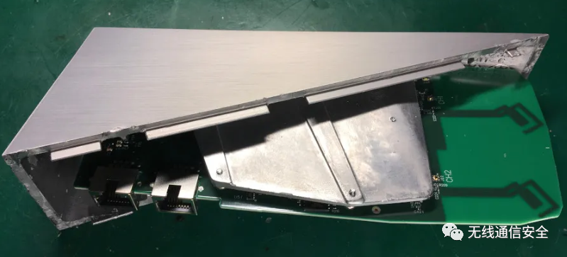
射频前端
让我们看看天线设计和射频前端。不知道那些射频屏蔽下到底是什么。但由于 SoC 包含完全集成的WLAN,因此罐内只有功率A放大器、低噪声 A放大器、滤波器和开关。
Ch0和Ch2天线设计源自原始路由器。但这是一个 3×3(3 TX,3 RX)MIMO无线电。这就是为什么我们在这里有第三个CH1天线。这是一个简单的贴片天线。新的天线布局有助于为最佳 MIMO 操作创建空间分集。这绝对比原来的路由器好。
标记的方形元件是射频双工器,就像这个一样。这些元件允许将 2.4 GHz 和 5 GHz 线路连接到单个天线。
https://media.digikey.com/pdf/Data%20Sheets/Walsin%20Technology%20PDFs/KFDIP2004L197B1U.pdf
这是双频WiFi路由器的典型布局。三个相同的通道:
有趣的是,CH1 2.4 GHz 组件位于第一个屏蔽层下方,而 5 GHz 位于第二个屏蔽层下方。WiFi系统特点:
2.4 GHz 802.11n 3×3 MIMO信道带宽,MHz:20、40
5 GHz 802.11ac 3×3 MU-MIMO信道带宽,MHz:20、40、80
最大客户端(802.11n + 802.11ac):255
请注意,这只是芯片的 MAC 表大小。这意味着该接入点最多可以同时容纳 255 个连接的客户端。但这并不意味着所有 255 个客户端都能有效工作。当然,他们没有。
发射功率和灵敏度
SoC 内置集成 PA 在 5GHz 时可输出高达 23.5 dBm。
RX 灵敏度约为 -94 dB。
不知道那些射频罐下面是什么,所以我们不知道射频前端的真实特征。我预计 25-27 dBm 左右的更高输出功率和 -94 -90 dB 左右的类似(或更低)RX 灵敏度。总的来说,它是一个很好的现代 WiFi 接入点。
以太网
有两条以太网线。第一个是 WAN,用于 Dishy 连接。WAN接口采用SoC内置以太网PHY。只有外部组件是强大的 PoE 磁性元件和电容器。
额外的外部 PHY 88E1512支持 LAN 接口。这是 Marvell 的 Alaska 系列 PHY。板上没有以太网磁性元件。
https://www.marvell.com/content/dam/marvell/en/public-collateral/transceivers/marvell-phys-transceivers-alaska-88e151x-datasheet.pdf
该 PHY 驱动外部以太网适配器内部的变压器。
该设备连接到 SoC 的 SGMII 线之一。
PoE控制器
Starlink GitHub 上有一个很好的问题。
https://github.com/SpaceExplorationTechnologies/starlink-wifi-gen2#Jobs
这是该区域的特写马赛克照片:
我们在这里可以看到它是一个用于打开和关闭 Dishy 电源的MOSFET 。小QFN IC应该是PoE控制器。
https://www.mccsemi.com/pdf/Products/MCU20P10(DPAK).pdf
50V 和 2A 电源意味着 Starlink 使用 4 对802.3bt PoE。这是最新的 PoE标准。我不确定 SpaceX 100% 是否遵循这里的标准。
https://www.analog.com/en/technical-articles/jumpstarting-ieee-802-3bts-poe.html
https://ieeexplore.ieee.org/document/8632920
不幸的是,我找不到有关 PoE PSE 控制器的任何信息。我怀疑它可能来自 LTC 阵容。甚至可能是LTPoE++。没有把握。
https://www.analog.com/en/technical-articles/ltpoe-extends-poe-to-90w-with-reliable-and-easy-to-use-standard.html
在右边,有一个运算放大器和许多晶体管。
https://www.onsemi.com/pdf/datasheet/ncs333-d.pdf
一个 0.05 欧姆的大 SMD 电阻器,绝对是分流器。这意味着运算放大器是一个电流测量电路。
基本上,运算放大器测量分流端子上的电压差。由于高阻抗,没有电流流向运算放大器输入。只是电压差而已。
通常,电流分流器直接连接到 PoE 控制器。但是,在这种情况下,出于某种原因,他们决定使用外部放大器。这可能是 PoE 控制器 IC 的要求。
或者,所有这些都可能是芯片短缺的影响🙂
有趣的是,运算放大器的 Vss 引脚没有直接接地。一个额外的电路将接地“提升”约 0.5 V,允许放大器测量较低的值,低至 0 V。
请原谅这些示意图的粗鲁。我没有时间建造它来缩放或绘制它。
我试图重新创建该区域的示意图。
当然,还有很多未知数。我没有板子,所以我无法追踪所有的线。另外,我无法识别某些组件。另外,可能存在错误识别的组件。
我用“?”标记了未知的行和有问题的组件象征。
Q1 MOSFET 为 Dishy 切换 50V 电源。两个晶体管上有一个驱动电路。正确驱动功率 MOSFET 始终很重要。
“Dishy PWR ON”应该连接到PoE控制器上,所以只有当控制器检测到连接在另一侧的PD控制器(Dishy)时才施加50V。运算放大器通道 1 测量0.05 欧姆分流器
上的 Dishy 电流。我不知道第二个运算放大器通道在做什么。它的非反相输入连接在某处。
两个通道的输出都连接到晶体管。该电路看起来像一个射极跟随器。我无法识别标记为“ST”的两个组件。它可能是一些 MOSFET,因此射极跟随器调节流过这些 MOSFET 的电流。
最后,该电路应连接到 PoE 控制器。它是针对 Dishy 短路和其他问题的硬件保护。
当然,有些线路可能会连接到 SoC 以监控来自软件的电压/电流。
STSAFE
Starlink存储库中还有一个问题:
https://github.com/SpaceExplorationTechnologies/starlink-wifi-gen2#Jobs
I2C 地址 0x20 处的设备做什么。
我们从上一篇文章中得知,这款设备是 STSAFE-A110 安全/认证芯片。该芯片在新路由器中做同样的工作,而且现在它是引导过程的一部分。
https://olegkutkov.me/2021/12/25/analysis-and-reverse-engineering-of-the-original-starlink-router
https://github.com/SpaceExplorationTechnologies/starlink-wifi-gen2/blob/main/ATF/plat/mediatek/mt7629/include/spacex_stsafe.icc.c
路由器框图
可能有一些不准确的地方,但总体上看起来是这样的。
固件
新固件基于LEDE (OpenWrt) 17.01 和 MediaTek SDK。SpaceX 团队声称他们正试图尽可能接近上游的 OpenWrt。
https://openwrt.org/releases/17.01/start
GitHub存储库包含几乎所有内容,除了专有的联发科技驱动程序和一些工具。此外,一些 SpaceX 代码仍然关闭,但存在二进制文件。
https://github.com/SpaceExplorationTechnologies/starlink-wifi-gen2
https://github.com/SpaceExplorationTechnologies/starlink-wifi-gen2/tree/main/payload/bazel-out/armv7l-opt-clang-12/bin/spacex/ux/wifi/wifi_control
另外,这次我们有 Docker 和一些额外的脚本。谢谢🙂
但这无助于构建存储库。一些 OpenWrt 文件丢失。另外,引导加载程序签名存在问题。
Starlink 路由器使用安全引导,因此需要证书才能使用引导加载程序二进制文件进行构建。当然,存储库中没有 SpaceX 证书。但是构建系统需要这个文件。这会破坏构建过程。
我决定引入一个额外的标志BUILD_BOOTLOADERS,来解决这个问题。此标志禁用引导加载程序的编译。
这两个问题在我在这里和那里的提交中都得到了解决。
https://github.com/olegkutkov/starlink-wifi-gen2/commit/aabbda684df21506c935abe62a8aa8b05a7f6385
https://github.com/olegkutkov/starlink-wifi-gen2/commit/2af2c6065ab1c10674e987f8dfc43c6de968d01e
系统从单个 NAND 芯片启动。第一阶段引导加载程序在 SoC ROM 内烧录。
NAND 包含一个第二阶段引导加载程序、u-boot、两个 Linux 内核副本和两个操作系统副本。加上一些额外的分区。
https://github.com/SpaceExplorationTechnologies/starlink-wifi-gen2/blob/main/openwrt/target/linux/mediatek/files/arch/arm/boot/dts/spacex-v2-1.dtsi
闪存布局:
| Partition name | Start offset | Length |
| BL2 | 0x00000 | 0x0080000 |
| InactiveFIP | 0x80000 | 0x0200000 |
| ActiveFIP | 0x280000 | 0x0200000 |
| Config | 0x480000 | 0x0080000 |
| Factory | 0x500000 | 0x0200000 |
| InactiveKernel | 0x2000000 | 0x2000000 |
| ActiveKernel | 0x4000000 | 0x2000000 |
| Storage | 0x6000000 | 0x1800000 |
BL2它是从 SoC ROM 开始的第二阶段引导加载程序。
此引导加载程序执行硬件的初始化:CPU、内存和安全性。
下一阶段是FIP容器中的u-boot 。从或中选择一个实例。该逻辑在上面的 STSAFE 章节中进行了描述。在这个阶段,BL2 验证 FIP 图像的签名。不引导无效或未签名的 FIP 映像。
https://github.com/SpaceExplorationTechnologies/starlink-wifi-gen2/tree/main/uboot
https://github.com/ARM-software/arm-trusted-firmware/blob/master/docs/design/firmware-design.rst#firmware-image-package-fip
U-boot 执行特定于供应商的初始化和例程,例如操作系统的恢复和引导。
分区InactiveKernel并ActiveKernel包含 OpenWrt 操作系统的 squashfs 映像。一是开机,二是之前版本的备份。也许这些分区名称是从联发科 SDK 派生的。
该Storage分区包含一个带有两个 UBIFS 分区的 UBI 映像。
https://github.com/ARM-software/arm-trusted-firmware/blob/master/docs/design/firmware-design.rst#firmware-image-package-fip
https://github.com/SpaceExplorationTechnologies/starlink-wifi-gen2/tree/main/uboot
这是 UBI配置文件。两个分区都在运行时挂载为 rw。
该系统作为一个常规的 OpenWrt 系统启动。SpaceX 特定的任务在First, a reverse filter is disabled
的末尾定义:etc/init.d/boot
首先,禁用反向过滤器:
https://tldp.org/HOWTO/Adv-Routing-HOWTO/lartc.kernel.rpf.html
下一步应用大量防火墙过滤器。
https://github.com/SpaceExplorationTechnologies/starlink-wifi-gen2/blob/main/openwrt/package/base-files/files/sbin/setup_iptables.sh
在最后阶段,配置Marvell 以太网 PHY。
https://github.com/SpaceExplorationTechnologies/starlink-wifi-gen2/blob/main/openwrt/package/base-files/files/sbin/configure_ephy.sh
此外,我们还有一个很酷的新登录横幅:
甚至还有乌克兰的特殊版本。谢谢SpaceX 的支持!
https://raw.githubusercontent.com/SpaceExplorationTechnologies/starlink-wifi-gen2/f592948af9cfd7c2a8c85cfcfa973b2b821419e2/openwrt/package/base-files/files/etc/banner.ua
wifi_control
与之前的路由器一样,所有路由器操作都由用 Go 语言编写的专有wifi_control守护进程控制。
https://github.com/SpaceExplorationTechnologies/starlink-wifi-gen2/tree/main/payload/bazel-out/armv7l-opt-clang-12/bin/spacex/ux/wifi/wifi_control
驱动程序 WiFi 配置以纯文本格式存储。该文件格式是 MediaTek 平台的典型格式。
https://github.com/SpaceExplorationTechnologies/starlink-wifi-gen2/blob/main/openwrt/package/mtk/drivers/wifi-profile/files/mt7629/mt7629.1.b1.5g.dat
我不确定这次是否使用了 wifi_control 二进制配置,但可能是的。
是否可以使用“旧”STSAFE 芯片在 Raspberry PI 上运行新的 wifi_control?当然!
wifi_control 正确检测到第一代平台并尝试配置 IPQ401x 系统。
(看看)Reboot reason 🙂
有趣的是,整个路由器的操作由单个文件控制 当该文件存在时,路由器切换到旁路模式:根本不运行,防火墙规则被清除,但出站流量除外。/tmp/enable_bypass_mode
wifi_control
https://github.com/SpaceExplorationTechnologies/starlink-wifi-gen2/blob/main/openwrt/package/base-files/files/sbin/setup_iptables.sh#L103
此外,wifi_control 守护进程运行一个内置的 Web 服务器。这个网络服务器是在“HTML 模板”标准 Go库上实现的。
https://pkg.go.dev/html/template
这是所有的 HTML 模板文件。JS 代码和 CSS 在附近目录中。
https://github.com/SpaceExplorationTechnologies/starlink-wifi-gen2/tree/main/payload/spacex/ux/wifi/wifi_control/templates
https://github.com/SpaceExplorationTechnologies/starlink-wifi-gen2/tree/main/payload/spacex/ux/wifi/wifi_control/static
所有这些文件都放在 OpenWrt squashfs 路径中。我们可以在那里找到很多有趣的东西。例如,路由器配置页面。它看起来像普通用户无法使用的工厂/维护模式页面:/etc/www/templates/
你可以看到 Go 模板而不是真实数据。
但最有趣的是网状拓扑页面。
https://github.com/SpaceExplorationTechnologies/starlink-wifi-gen2/blob/main/payload/spacex/ux/wifi/wifi_control/templates/mesh_topology.html
看起来 SpaceX 正在实施 WiFi 网状网络技术。这意味着他们将单独销售路由器或其变体。
我想这已经不是什么大秘密了,而且一切都在开放的存储库中。这就是我写这篇文章的原因。
看起来整个页面只是一个正在进行的工作。当然,如果在浏览器中打开此页面,则不会显示任何内容。
我们需要提供数据才能看到一些东西。
我分析了 JS代码,发现页面需要特定格式的 JSON 来显示IEEE 1905拓扑。
https://github.com/SpaceExplorationTechnologies/starlink-wifi-gen2/blob/main/payload/spacex/ux/wifi/wifi_control/static/js/topology-visualizer.js
https://en.wikipedia.org/wiki/IEEE_1905
主要数据源是topology-merger.jstopoJSON中的对象
https://github.com/SpaceExplorationTechnologies/starlink-wifi-gen2/blob/main/payload/spacex/ux/wifi/wifi_control/static/js/topology-merger.js
让我们添加一些随机数据:
这是一个有趣的页面。所有对象都是浮动的,并且可以拖动所有内容。
3、黑客破解starlink路由器地面站固件提取及分析
在玩了几个小时之后,是时候弄脏我们的手并拆卸 UT。
UART接口
U-Boot 2020.04-gddb7afb (Apr 16 2021 - 21:10:45 +0000)
Model: Catson
DRAM: 1004 MiB
MMC: Fast boot:eMMC: 8xbit - div2
stm-sdhci0: 0
In: nulldev
Out: serial
Err: serial
CPU ID: 0x00020100 0x87082425 0xb9ca4b91
Detected Board rev: #rev2_proto2
sdhci_set_clock: Timeout to wait cmd & data inhibit
FIP1: 3 FIP2: 3
BOOT SLOT B
Net: Net Initialization Skipped
No ethernet found.
*
+
+ +
+ +
+ +
+ + + + + + +
+ + + +
+ + + +
+ + +
+ + +
+ + +
+ + + +
+ + + +
+ + + + + + + + + +
Board: SPACEX CATSON UTERM
======================================
= Type 'falcon' to stop boot process =
======================================
继续引导过程,我们可以看到 U-Boot 从存储在嵌入式多媒体卡 (eMMC) 上的扁平化 uImage 树 (FIT) 映像中加载内核、ramdisk 和扁平化设备树 (FDT)。
我们还可以看到正在检查内核、ramdisk 和 FDT 的完整性 (SHA256) 和真实性 (RSA 2048)。虽然我们必须执行更多测试,但似乎从早期的 ROM 引导加载程序一直到 Linux 操作系统都实现了完整的可信引导链 (TF-A)。
switch to partitions #0, OK
mmc0(part 0) is current device
MMC read: dev # 0, block # 98304, count 49152 ... 49152 blocks read: OK
## Loading kernel from FIT Image at a2000000 ...
Using '[email protected]' configuration
Verifying Hash Integrity ... sha256,rsa2048:dev+ OK
Trying '[email protected]' kernel subimage
Description: compressed kernel
Created: 2021-04-16 21:10:45 UTC
Type: Kernel Image
Compression: lzma compressed
Data Start: 0xa20000dc
Data Size: 3520634 Bytes = 3.4 MiB
Architecture: AArch64
OS: Linux
Load Address: 0x80080000
Load Size: unavailable
Entry Point: 0x80080000
Hash algo: sha256
Hash value: 5efc55925a69298638157156bf118357e01435c9f9299743954af25a2638adc2
Verifying Hash Integrity ... sha256+ OK
## Loading ramdisk from FIT Image at a2000000 ...
Using '[email protected]' configuration
Verifying Hash Integrity ... sha256,rsa2048:dev+ OK
Trying '[email protected]' ramdisk subimage
Description: compressed ramdisk
Created: 2021-04-16 21:10:45 UTC
Type: RAMDisk Image
Compression: lzma compressed
Data Start: 0xa2427f38
Data Size: 8093203 Bytes = 7.7 MiB
Architecture: AArch64
OS: Linux
Load Address: 0xb0000000
Load Size: unavailable
Entry Point: 0xb0000000
Hash algo: sha256
Hash value: 57020a8dbff20b861a4623cd73ac881e852d257b7dda3fc29ea8d795fac722aa
Verifying Hash Integrity ... sha256+ OK
Loading ramdisk from 0xa2427f38 to 0xb0000000
WARNING: 'compression' nodes for ramdisks are deprecated, please fix your .its file!
## Loading fdt from FIT Image at a2000000 ...
Using '[email protected]' configuration
Verifying Hash Integrity ... sha256,rsa2048:dev+ OK
Trying '[email protected]' fdt subimage
Description: rev2 proto 2 device tree
Created: 2021-04-16 21:10:45 UTC
Type: Flat Device Tree
Compression: uncompressed
Data Start: 0xa23fc674
Data Size: 59720 Bytes = 58.3 KiB
Architecture: AArch64
Load Address: 0x8f000000
Hash algo: sha256
Hash value: cca3af2e3bbaa1ef915d474eb9034a770b01d780ace925c6e82efa579334dea8
Verifying Hash Integrity ... sha256+ OK
Loading fdt from 0xa23fc674 to 0x8f000000
Booting using the fdt blob at 0x8f000000
Uncompressing Kernel Image
Loading Ramdisk to 8f848000, end 8ffffe13 ... OK
ERROR: reserving fdt memory region failed (addr=b0000000 size=10000000)
Loading Device Tree to 000000008f836000, end 000000008f847947 ... OK
WARNING: ethact is not set. Not including ethprime in /chosen.
Starting kernel ...
引导过程的其余部分包含一些其他有趣的信息。
例如,我们可以看到内核命令行参数以及一些分区的起始地址和长度。此外,我们可以看到 SoC 包含 4 个 CPU 内核。
[ 0.000000] 000: Detected VIPT I-cache on CPU0
[ 0.000000] 000: Built 1 zonelists, mobility grouping on. Total pages: 193536
[ 0.000000] 000: Kernel command line: rdinit=/usr/sbin/sxruntime_start mtdoops.mtddev=mtdoops console=ttyAS0,115200 quiet alloc_snapshot trace_buf_size=5M rcutree.kthread_prio=80 earlycon=stasc,mmio32,0x8850000,115200n8 uio_pdrv_genirq.of_id=generic-uio audit=1 SXRUNTIME_EXPECT_SUCCESS=true blkdevparts=mmcblk0:[email protected](BOOTFIP_0),[email protected](BOOTFIP_1),[email protected](BOOTFIP_2),[email protected](BOOTFIP_3),[email protected](BOOTTERM1),[email protected](BOOTTERM2),[email protected](BOOT_A_0),[email protected](BOOT_B_0),[email protected](BOOT_A_1),[email protected](BOOT_B_1),[email protected](UBOOT_TERM1),[email protected](UBOOT_TERM2),[email protected](SXID),[email protected](KERNEL_A),[email protected](CONFIG_A),[email protected](KERNEL_B),[email protected](CONFIG_B),[email protected](SX_A),[email protected](SX_B),[email protected](VERSION_INFO_A),[email protected](VERSION_INFO_B),0x00020000
[ 0.000000] 000: audit: enabled (after initialization)
[ 0.000000] 000: Dentry cache hash table entries: 131072 (order: 9, 2097152 bytes, linear)
[ 0.000000] 000: Inode-cache hash table entries: 65536 (order: 7, 524288 bytes, linear)
[ 0.000000] 000: mem auto-init: stack:off, heap alloc:off, heap free:off
[ 0.000000] 000: Memory: 746884K/786432K available (6718K kernel code, 854K rwdata, 1648K rodata, 704K init, 329K bss, 39548K reserved, 0K cma-reserved)
[ 0.000000] 000: SLUB: HWalign=64, Order=0-3, MinObjects=0, CPUs=4, Nodes=1
[ 0.000000] 000: ftrace: allocating 23664 entries in 93 pages
[ 0.000000] 000: rcu: Preemptible hierarchical RCU implementation.
[ 0.000000] 000: rcu: RCU event tracing is enabled.
[ 0.000000] 000: rcu: RCU restricting CPUs from NR_CPUS=8 to nr_cpu_ids=4.
[ 0.000000] 000: rcu: RCU priority boosting: priority 80 delay 500 ms.
[ 0.000000] 000: rcu: RCU_SOFTIRQ processing moved to rcuc kthreads.
[ 0.000000] 000: No expedited grace period (rcu_normal_after_boot).
[ 0.000000] 000: Tasks RCU enabled.
[ 0.000000] 000: rcu: RCU calculated value of scheduler-enlistment delay is 100 jiffies.
[ 0.000000] 000: rcu: Adjusting geometry for rcu_fanout_leaf=16, nr_cpu_ids=4
[ 0.000000] 000: NR_IRQS: 64, nr_irqs: 64, preallocated irqs: 0
[ 0.000000] 000: random: get_random_bytes called from start_kernel+0x33c/0x4b0 with crng_init=0
[ 0.000000] 000: arch_timer: cp15 timer(s) running at 60.00MHz (virt).
[ 0.000000] 000: clocksource: arch_sys_counter: mask: 0xffffffffffffff max_cycles: 0x1bacf917bf, max_idle_ns: 881590412290 ns
[ 0.000000] 000: sched_clock: 56 bits at 60MHz, resolution 16ns, wraps every 4398046511098ns
[ 0.008552] 000: Calibrating delay loop (skipped), value calculated using timer frequency..
[ 0.016871] 000: 120.00 BogoMIPS (lpj=60000)
[ 0.021129] 000: pid_max: default: 32768 minimum: 301
[ 0.026307] 000: Mount-cache hash table entries: 2048 (order: 2, 16384 bytes, linear)
[ 0.034005] 000: Mountpoint-cache hash table entries: 2048 (order: 2, 16384 bytes, linear)
[ 0.048359] 000: ASID allocator initialised with 32768 entries
[ 0.050341] 000: rcu: Hierarchical SRCU implementation.
[ 0.061390] 000: smp: Bringing up secondary CPUs ...
[ 0.078677] 001: Detected VIPT I-cache on CPU1
[ 0.078755] 001: CPU1: Booted secondary processor 0x0000000001 [0x410fd034]
[ 0.095799] 002: Detected VIPT I-cache on CPU2
[ 0.095858] 002: CPU2: Booted secondary processor 0x0000000002 [0x410fd034]
[ 0.112970] 003: Detected VIPT I-cache on CPU3
[ 0.113025] 003: CPU3: Booted secondary processor 0x0000000003 [0x410fd034]
[ 0.113160] 000: smp: Brought up 1 node, 4 CPUs
[ 0.113184] 000: SMP: Total of 4 processors activated.
最后,当 UT 完成启动过程时,我们会看到登录提示:
Development login enabled: no
SpaceX User Terminal.
user1 login:
在尝试猜测有效的登录凭据时,我们开始意识到这个 UART 接口不太可能轻松获胜。我们必须更深入。
拆解:2级
UT 的背面金属盖围绕外边缘粘在组件上,并在金属盖的肋条和下面的 PCB 之间涂上额外的胶水。为了松开金属盖边缘的胶水,我们使用了热风枪、撬具、异丙醇和很大的耐心。具体来说,我们首先对一小部分进行加热,使用撬工具松开该部分,添加 IPA 以帮助溶解胶水和另一轮撬工具。取下金属盖后,我们看到一块直径约 55 厘米的巨大 PCB。
我们感兴趣的部分如下图所示。带有金属盖的倒装芯片 BGA 封装是该板上的主要 SoC(标记:ST GLLCCOCA6BF)。不出所料,SoC 以 eMMC 芯片的形式连接到一些易失性 DRAM 存储和非易失性闪存存储。
识别 eMMC 测试点
在线倾倒 eMMC
解压原始 eMMC 转储
#define SPACEX_CATSON_COMMON_BOOT_SETTINGS \
"kernel_boot_addr=" __stringify(CATS_KERNEL_BOOT_ADDR) "\0" \
"kernel_load_addr=" __stringify(CATS_KERNEL_LOAD_ADDR) "\0" \
"kernel_offset_a=" __stringify(CATS_KERNEL_A_OFFSET) "\0" \
"kernel_offset_b=" __stringify(CATS_KERNEL_B_OFFSET) "\0" \
"kernel_size=" __stringify(CATS_KERNEL_A_SIZE) "\0" \
"setup_burn_memory=mw.q " __stringify(CATS_TERM_SCRATCH_ADDR) " 0x12345678aa640001 && " \
"mw.l " __stringify(CATS_TERM_LOAD_ADDR) " 0xffffffff " __stringify(CATS_BOOTTERM1_SIZE) " && " \
"mw.l " __stringify(CATS_TERM_TOC_SER_ADDR) " " __stringify(CATS_TERM_TOC_SER_VAL) "\0" \
"startkernel=unecc $kernel_load_addr $kernel_boot_addr && bootm $kernel_boot_addr${boot_type}\0" \
"stdin=nulldev\0"
#define SPACEX_CATSON_BOOT_SETTINGS \
SPACEX_CATSON_COMMON_BOOT_SETTINGS \
"_emmcboot=mmc dev " __stringify(CATS_MMC_BOOT_DEV) " " __stringify(CATS_MMC_BOOT_PART) " && " \
"mmc read8 $kernel_load_addr ${_kernel_offset} $kernel_size && " \
"run startkernel\0" \
"emmcboot_a=setenv _kernel_offset $kernel_offset_a && run _emmcboot\0" \
"emmcboot_b=setenv _kernel_offset $kernel_offset_b && run _emmcboot\0"
的定义startkernel特别有趣,因为它显示了加载内核的地址是如何传递给名为unecc. 从unecc命令定义中可以清楚地看出,该功能正在对从 eMMC 读取的数据执行纠错。
U_BOOT_CMD(
unecc, 3, 0, do_unecc,
"Unpacks an ECC volume; increments internal ECC error counter on error",
"<source> <target>\n"
"\tReturns successfully if the given source was successfully\n"
"\tunpacked to the target. This will fail if the given source\n"
"\tis not an ECC volume. It will succeed if bit errors were\n"
"\tsuccessfully fixed.\n"
"\t<source> and <target> should both be in hexadecimal.\n"
);
该unecc命令调用do_unecc实现的函数unecc.c。最终这将导致调用中ecc_decode_one_pass定义的函数ecc.c。
/**
* Decodes an ECC protected block of memory. If the enable_correction
* parameter is zero, it will use the MD5 checksum to detect errors and will
* ignore the ECC bits. Otherwise, it will use the ECC bits to correct any
* errors and still use the MD5 checksum to detect remaining problems.
*
* @data: Pointer to the input data.
* @size: The length of the input data, or 0 to read until the
* end of the ECC stream.
* @dest: The destination for the decoded data.
* @decoded[out]: An optional pointer to store the length of the decoded
* data.
* @silent: Whether to call print routines or not.
* @enable_correction: Indicates that the ECC data should be used
* to correct errors. Otherwise the MD5 checksum
* will be used to check for an error.
* @error_count[out]: Pointer to an integer that will be incremented
* by the number of errors found. May be NULL.
* Unused if !enable_correction.
*
* Return: 1 if the block was successfully decoded, 0 if we had a
* failure, -1 if the very first block didn't decode (i.e. probably
* not an ECC file)
*/
static int ecc_decode_one_pass(const void *data, unsigned long size, void *dest,
unsigned long *decoded, int silent,
int enable_correction, unsigned int *error_count)
ecc.h包含几个相关定义:
#else /* !NPAR */
#define NPAR 32
#endif /* NPAR */
/*
* These options must be synchronized with the userspace "ecc"
* utility's configuration options. See ecc/trunk/include/ecc.h in the
* "util" submodule of the platform.
*/
#define ECC_BLOCK_SIZE 255
#define ECC_MD5_LEN 16
#define ECC_EXTENSION "ecc"
#define ECC_FILE_MAGIC "SXECCv"
#define ECC_FILE_VERSION '1'
#define ECC_FILE_MAGIC_LEN (sizeof(ECC_FILE_MAGIC) - 1)
#define ECC_FILE_FOOTER_LEN sizeof(file_footer_t)
#define ECC_DAT_SIZE (ECC_BLOCK_SIZE - NPAR - 1)
#define ECC_BLOCK_TYPE_DATA '*'
#define ECC_BLOCK_TYPE_LAST '$'
#define ECC_BLOCK_TYPE_FOOTER '!'
最后归结为,在这个实现中,一个受 ECC 保护的内存块以魔术头值SXECCv开头,后跟一个版本字节 ( 1)。这个神奇的值标志着 ECC 保护数据的开始,也标志着头块的开始。标头块本身包含(除了魔法值和版本字节)、215 字节的数据、星号 ( *) 和 32 字节的 ECC 代码字。
头块后面是多个数据块。这些数据块中的每一个都是 255 字节长,包含 222 字节的数据,后跟一个星号 ( *) 和 32 字节的 ECC 代码字。最后一个数据块包含一个美元符号 ( $) 而不是星号,然后是最后一个页脚块。此页脚块以感叹号 ( !) 开头,后跟 ECC 受保护内存块(4 字节)中的数据字节数和这些数据字节的 MD5 摘要。
至此应该清楚为什么 Binwalk 没有成功提取内核、initramfs 和 FDT。Binwalk 能够获取指示特定文件开始的魔法值,但文件的每个块都有阻止 Binwalk 提取它的附加数据。在使用 Binwalk 提取图像之前,我们使用了一个简单的 Python 脚本来删除额外的 ECC 数据。同样,我们现在也可以使用 dumpimage 来获取有关 FIT 图像的更多信息。
FIT 图像和电路板修订
以下代码段包含一些转储图像输出。FIT 映像包含 13 个引导配置,所有配置都使用相同的内核和 initramfs 映像,但使用不同的扁平设备树 (FDT)。
FIT description: Signed dev image for catson platforms
Created: Fri Apr 16 23:10:45 2021
Image 0 ([email protected])
Description: compressed kernel
Created: Fri Apr 16 23:10:45 2021
Type: Kernel Image
Compression: lzma compressed
Data Size: 3520634 Bytes = 3438.12 KiB = 3.36 MiB
Architecture: AArch64
OS: Linux
Load Address: 0x80080000
Entry Point: 0x80080000
Hash algo: sha256
Hash value: 5efc55925a69298638157156bf118357e01435c9f9299743954af25a2638adc2
Image 12 ([email protected])
Description: rev2 proto 2 device tree
Created: Fri Apr 16 23:10:45 2021
Type: Flat Device Tree
Compression: uncompressed
Data Size: 59720 Bytes = 58.32 KiB = 0.06 MiB
Architecture: AArch64
Load Address: 0x8f000000
Hash algo: sha256
Hash value: cca3af2e3bbaa1ef915d474eb9034a770b01d780ace925c6e82efa579334dea8
Image 15 ([email protected])
Description: compressed ramdisk
Created: Fri Apr 16 23:10:45 2021
Type: RAMDisk Image
Compression: lzma compressed
Data Size: 8093203 Bytes = 7903.52 KiB = 7.72 MiB
Architecture: AArch64
OS: Linux
Load Address: 0xb0000000
Entry Point: 0xb0000000
Hash algo: sha256
Hash value: 57020a8dbff20b861a4623cd73ac881e852d257b7dda3fc29ea8d795fac722aa
Default Configuration: '[email protected]'
Configuration 0 ([email protected])
Description: default
Kernel: [email protected]
Init Ramdisk: [email protected]
FDT: [email protected]
Sign algo: sha256,rsa2048:dev
Sign value: bb34cc2512d5cd3b5ffeb5acace0c1b3dd4d960be3839c88df57c7aeb793ad73a74e87006efece4e9f1e31edbb671e2c63dc4cdcb1a2f55388d83a11f1074f21a1e48d81884a288909eb0c9015054213e5e74cbcc6a6d2617a720949dcac3166f1d01e3c2465d8e7461d14288f1a0abef22f80e2745e7f8499af46e8c007b825d72ab494f104df57433850f381be793bfe06302473269d2f45ce2ff2e8e4439017c0a94c5e7c6981b126a2768da555c86b2be136d4f5785b83193d39c9469bd24177be6ed3450b62d891a30e96d86eee33c2cbfc549d3826e6add36843f0933ced7c8e23085ee6106e3cc2af1e04d2153af5f371712854e91c8f33a4ea434269
从 U-Boot 代码 ( spacex_catson_uterm.c) 可以清楚地看出,引导配置是根据 5 个 GPIO 引脚的状态决定的。
/**
* Check board ID GPIOs to find board revision.
* The board IDs are mapped as follows
* id_b0:pio12[2]
* id_b1:pio12[3]
* id_b2:pio12[0]
* id_b3:pio12[1]
* id_b4:pio20[4]
*/
u32 pio12 = readl(BACKBONE_PIO_A_PIO2_PIN);
u32 pio20 = readl(BACKBONE_PIO_B_PIO0_PIN);
u32 board_id = (((pio12 >> 2) & 1) << 0) |
(((pio12 >> 3) & 1) << 1) |
(((pio12 >> 0) & 1) << 2) |
(((pio12 >> 1) & 1) << 3) |
(((pio20 >> 4) & 1) << 4);
/*
* https://confluence/display/satellites/User+Terminal%3A+Catson+ID+Bits
*/
switch (board_id)
{
case 0b11111:
board_rev_string = BOARD_REV_1_1P3;
break;
case 0b11100:
board_rev_string = BOARD_REV_1_2P1;
break;
case 0b11000:
board_rev_string = BOARD_REV_1_2P2;
break;
case 0b10100:
board_rev_string = BOARD_REV_1_3P0;
break;
case 0b10000: /* rev1 pre-production */
board_rev_string = BOARD_REV_1_PRE_PROD;
break;
case 0b11110: /* rev1 production */
board_rev_string = BOARD_REV_1_PROD;
break;
case 0b00001:
board_rev_string = BOARD_REV_2_0P0;
break;
case 0b00010:
board_rev_string = BOARD_REV_2_1P0;
break;
case 0b00011:
board_rev_string = BOARD_REV_2_2P0;
break;
}
}
printf("Detected Board rev: %s\n", board_rev_string);
下图显示了这些引脚被拉高/拉低以指示电路板修订的位置。请注意,从早期的串行引导日志中,我们的 UT 使用rev2_proto2配置 ( case 0b00011) 引导。在最近的视频中,Colin O'Flynn 将其中一些引脚拉高/拉低,可以观察到 UT 尝试使用不同的 FIT 配置启动,因此使用不同的设备树[5]。我们比较了一些 FDT,但没有发现任何从安全角度来看有趣的差异。
初看固件
登录提示
回想一下,在启动过程完成后,我们会看到登录提示。对于进一步的研究,获得登录的能力将是有用的,允许我们与实时系统进行交互。但是,通过查看影子文件,可以清楚地看出不允许任何用户登录。
在引导期间,UT 确实会读取保险丝以确定它是否是开发硬件。如果 UT 未融合,它将为 root 用户设置密码,允许登录。
出售给消费者的 Starlink UT 当然是生产融合的,禁用登录提示。
root:*:10933:0:99999:7:::
bin:*:10933:0:99999:7:::
daemon:*:10933:0:99999:7:::
sync:*:10933:0:99999:7:::
halt:*:10933:0:99999:7:::
uucp:*:10933:0:99999:7:::
operator:*:10933:0:99999:7:::
ftp:*:10933:0:99999:7:::
nobody:*:10933:0:99999:7:::
sshd:*:::::::
开发硬件
开发硬件经常落入坏人之手[6, 7]。SpaceX 的工程师考虑了这种情况,似乎试图主动检测不再受其控制的未融合开发硬件。开发硬件的地理围栏只能在某些预定义的区域工作,其中大部分显然是 SpaceX 的位置。如果在这些预定义的地理围栏之外使用开发硬件,SpaceX 可能会收到通知。
有趣的是,其中一些地理围栏似乎与 SpaceX 没有明确的联系。虽然我们不会在这里透露这些位置,但我会说这SNOW_RANCH看起来是一个使用开发硬件的好位置。
安全元件
从固件中的参考资料可以清楚地看出(我们的修订版)UT 包含STMicroelectronics STSAFE安全元件。安全元件的用途尚不完全清楚,但它可用于远程验证 UT。
https://www.st.com/en/secure-mcus/stsafe-a110.html
系统级芯片
有人问正在使用哪种处理器:答案是四核 Cortex-A53,每个内核都被分配了一个特定的任务。
############################
# System Information
############################
#
# The user terminal phased-array computers are Catson SoCs with a quad-core
# Cortex-A53.
#
# We dedicate one core to control, while leaving the other three to handle
# interrupts and auxiliary processes.
#
# CPU 0: Control process.
# CPU 1: Lower-MAC RX process.
# CPU 2: Lower-MAC TX process.
# CPU 3: PhyFW and utility core - interrupts, auxiliary processes, miscellaneous
下一步是什么
现在就是这样。如果有兴趣,我们可能会继续研究 Starlink UT,并在未来的博客文章中提供更多详细信息。在撰写本文时,我们能够在 UT 上获得一个 root shell,但现在公开分享有关该问题的更多信息还为时过早。
4、黑客疯狂对starlink地面站和路由器暴力拆解
视频一部分花絮
https://github.com/mikeonspace/dishy
黑客玩的硬件
https://bh2017.exploitee.rs/Hacking_Hardware_With_A_10_Reader-wp.pdf
https://bh2017.exploitee.rs/Hacking_Hardware_With_A_10_Reader.pdf
参考材料
3、W25N01GV NAND 数据表
https://www.winbond.com/resource-files/W25N01GV%20Rev%20Q%20051721.pdf
4、黑客使用测信道攻击工具
5、黑客玩的硬件
https://bh2017.exploitee.rs/Hacking_Hardware_With_A_10_Reader-wp.pdf
https://bh2017.exploitee.rs/Hacking_Hardware_With_A_10_Reader.pdf
6、Starlink地面站用户手册
7、 MikeOnSpace – Starlink Dish 拆解!– 第 1 部分 –
https://youtu.be/QudtSo5tpLk
8、 Ken Keiter – Starlink 拆解:DISHY DESTROYED!–
https://youtu.be/iOmdQnIlnRo
9、信号路径 – Starlink Dish 相控阵设计、架构和射频深入分析 –
https://youtu.be/h6MfM8EFkGg
10、 MikeOnSpace – Starlink Dish TEARDOWN!– 第 2 部分 –
https://youtu.be/38_KTq8j0Nw
11、 Colin O'Flynn – Starlink Dishy (Rev2 HW) 拆解第 1 部分 – UART、重置、启动故障 – https://youtu.be/omScudUro3s
如有侵权请联系:admin#unsafe.sh